Table of Contents
Advertisement
Quick Links
Advertisement
Table of Contents

Related Manuals for Discrete Wireless MARCUS

Summary of Contents for Discrete Wireless MARCUS
- Page 1 MARCUS Installation Guide MARCUS Radio Module Version 2.4...
- Page 2 TRADEMARKS MARCUS is a service mark of Discrete Wireless. All other trademarks and service marks contained are the property of their respective owners. 2000-2002 Discrete Wireless All Rights Reserved.
-
Page 3: Table Of Contents
Hyper Terminal / Field Laptop Setup Hyper Terminal (Advanced Diagnostics) APPENDIX A: LOADING NEW FIRMWARE APPENDIX B: INSTALLATION OF THE MARCUS PTO/IDLE SENSOR 21 10 APPENDIX C: INSTALLATION INFORMATION SHEET APPENDIX D: TECHNICAL SPECIFICATIONS APPENDIX E: TECHNICAL PICTURES OF MARCUS... - Page 4 4.2 Example Placement of MARCUS Radio Module inside dashboard 4.3 Vehicle Fuse box 4.4 Example of Proper wrap of extra wire 4.5 Image of installed MARCUS Radio Module just before dashboard is replaced 5.2.1 Proper use of in-line power crimp 5.3.1 Proper placement of electrical ground wire 7.2.1 Hyper Terminal “Connect To”...
-
Page 5: Introduction
Radio Module is optimized to be utilized on the Cingular Interactive Intelligent Wireless Data Network in the U.S. and other 900mhz Mobitex based Packet Data Networks. In addition, this manual describes how to install and operate MARCUS Radio Module. Overview ... - Page 6 Also included, are the separate power connection cable and GPS antenna with cables. A listing of all these components their size and specification is given in Appendix B. The box enclosure exterior measurements and weight for each MARCUS Radio Module is given below: MARCUS Radio Module –...
-
Page 7: Equipment And Tools
2. Equipment and Tools The following is a general list of tools and supplies required for installation of the MARCUS Radio Module. 2.1 Recommended Equipment 2.2 Recommended Supplies Voltmeter Electrical tape 12 Volt circuit tester Double sided tape Screwdrivers (standard, Phillips, torx,... -
Page 8: Antennas
3. Antennas 3.1 General Antenna Guidelines The general guidelines for proper antenna placement are the following: GPS Antenna As a general rule, the placement of the GPS antenna must have a clear view of a large portion of the sky in order to be able to receive GPS satellite data. It is recommended that the GPS antenna have a clear view of at least 40 % of the sky. -
Page 9: Rf Antenna
If there are other radio antennas on the vehicle, position the MARCUS RF transmission antenna at least 18 inches away. You should always refer to the antenna manufacturer’s guidelines that will be included with the antenna packaging. - Page 10 MAXRAD M-NC 3/4 Permanent hole mount w 17' cable no connector. Tessco Order number 80834 Requires a SMA connector MAXRAD permanent body mount for 3/4" hole. Includes 17 foot RG- 58A/U cable. Order desired connector separately. Motorola-style mounts install in a 3/4" hole. Feature a 1-1/8"-18 thread and nickel-plated brass nut.
- Page 11 Antenna Specialists APG874.3 "On-Glass" Antenna 3 dB with 15' cable 890-960 MHz Tessco Order number 48531 Requires a SMA connector Frequency (MHz)/ 890-960 Product Narrative On Glass IV low power antenna with enclosed coil whip. Features a small mounting foot for maximum efficiency especially between defroster wires, solid state coupling box and a mini UHF connector on the coupler Gain (dB) 3 Maximum Power (Watts)
-
Page 12: Radio Module Installation Location
4. Radio Module Location The MARCUS Radio Module placement is dependant on several factors. the type of vehicle the placement of the antennas the availability of a constant 12 volt power supply In most vehicles, the MRM can be placed inside or underneath the dashboard. - Page 13 A constant power source is essential in the retention of GPS data inside the MARCUS unit, and is REQUIRED. Be sure to verify that the power source you have chosen will work when the vehicle is not running, and the keys are removed.
-
Page 14: Vehicle Wiring
(Above is the MARCUS Radio Module just before final placement) Fasten the MRM with screws using the pre-drilled holes on the fins of the unit, securely tie-wrap unit to a permanent structure. Safely tie wrap and store any extra cable around the unit. -
Page 15: Power Specifications
The power connector on the unit is a female Molex plug with 6 pins, of which two are used to power the MARCUS unit, and four pins are left available for sensor installations. This mates with the male Molex connector attached to the power cable. The power cable connector has a red + VDC lead and a black ground lead. - Page 16 3 solid green or red lights on the face of the MARCUS Radio Module. GPS and RF coverage can also be determined when HyperTerminal is actively connected to the module (see also Troubleshooting).
-
Page 17: Troubleshooting An Installation
3 minutes, vehicle may be out of coverage, or not responding. Check the “Account Information” tab on the Discrete Wireless, Inc. website to ensure the proper MAN# is entered for the vehicle, and that all information about the mobile is correct. -
Page 18: Hyper Terminal / Field Laptop Setup
For Windows ME, 2000: 32 MB of RAM (minimum) Software Required: HyperTerminal -For communication with The MARCUS Radio Module (MRM); you must use HyperTerminal. -To set up a HyperTerminal connection, click Start on Windows bar, then programs, then accessories, communications, and select HyperTerminal Once HyperTerminal is open select the following: 1. - Page 19 7.3 for instructions on using Hyper Terminal once the mobile is installed. (note: It is not required that a laptop be used to install The MARCUS Radio Module. The information obtained through the use of Hyper Terminal may be helpful in troubleshooting any problems with the installation or with the area of the country the installation is taking place.
-
Page 20: Hyper Terminal (Advanced Diagnostics)
In the event that a mobile’s program is erased, the unit will need to have its firmware loading again by mailing it to Discrete Wireless, or sending the mobile back to your Dealer. -
Page 21: Appendix A: Loading New Firmware
3. Place the firmware files into that folder by either cut and paste or un-zipping the files into that location. 4. Connect a serial cable to the computer and to the MARCUS unit. If you have two serial ports, use port COM 1. -
Page 22: Appendix B: Installation Of The Marcus Pto/Idle Sensor
Discrete Wireless at customersupport@discretewireless.net or call 404-365-2080. Please be prepared to supply the type of sensor install, (PTO or IDLE) and the MAN# of the MARCUS unit the sensor will be used with.) Installing the MARCUS PTO Sensor 1) Determine the nature of the PTO device and where to find a good +12 volt DC hot lead when the device is activated. - Page 23 2) If powering up the MARCUS unit for the first time, it could take a few minutes before all lights become solid. If powering up inside a garage, or under cover of some kind, the MSG light may not come on.
- Page 24 APPENDIX C: Example of a MARCUS Install Field Report Detail of Services Provided Per Vehicle MAINTENANCE FIRMWARE NSTALL INSTALL Field Report Number: Detail Description Serial No. Location Of Mobile Power Source Radio Ant SKU Mount SKU Firmware...
-
Page 25: Appendix D: Technical Specifications
Appendix D: Technical Specifications System/ Manufacturer Description Component MARCUS Discrete Wireless, MARCUS Radio Module Radio Inc. Dimension: 4” x 3” x 1.385” Module Weight: 1.00 pound Trimble L1 frequency, C/A code, 8 channel continuous tracking Receiver receiver Accuracy: <25 m SEP without SA... - Page 26 Wireless Modem MARCUS Radio Module RIM 902M (Research In Motion) OEM Radio Modem Operating Frequency: Transmit 896-902 MHz Receive 935-941 MHz Transmit Power: 2.0 Watts @ antenna port Power Supply: 4.1-4.75 volts 10 micro amps, sleep mode 0.2 mA, battery stand-by mode...
-
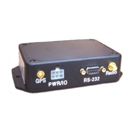
Page 27: Appendix E: Technical Pictures Of Marcus
Power - + 12 Volts DC on bottom right pin and Ground on top right pin Center Right Connector (9 Pin): RS-232 - use supplied 9-pin RS-232 connector Bottom Right Connector (SMA): Radio Antenna If you have any other questions, please contact Discrete Wireless Customer Support at customersupport@discretewireless.net or call 404-365-2080.
Need help?
Do you have a question about the MARCUS and is the answer not in the manual?
Questions and answers