Table of Contents
Advertisement
Advertisement
Table of Contents

Related Manuals for Discrete Wireless MARCUS 3G GPRS

Summary of Contents for Discrete Wireless MARCUS 3G GPRS
- Page 1 MARCUS® 3G Rev W2 Radio Module Installation Manual MARCUS ® 3G GPRS Radio Module...
- Page 2 This installation guide is published and copyrighted by Discrete Wireless, Inc. Information and specifications contained in this document are subject to change without notice and do not represent commitments on the part of Discrete Wireless. Under copyright laws, no part of this user’s guide may be reproduced or transmitted...
-
Page 3: Table Of Contents
Contents____________________________________________________ This manual covers the following: INTRODUCTION ® Introduction to the MARCUS 3G Radio Module Overview ® MARCUS 3G Radio Module (MRM) Hardware ® MARCUS 3G Wiring Diagrams EQUIPMENT AND TOOLS Recommended Tools Recommended Supplies ANTENNAS General Antenna Guidelines GPS Antenna RF Antenna Combo GPS/RF antenna VEHICLE WIRING... -
Page 4: Introduction
Discrete Wireless Gateway through a wireless communication link. The Discrete Wireless Gateway is capable of controlling and monitoring multiple mobile devices. The position data received from the mobile devices is transferred to the Discrete Wireless Gateway where it is displayed on a Geographical Information System (GIS) utilizing mapping technology within ®... - Page 5 The mobile devices consist of a nylon plastic engineered housing containing the electronic components. This includes the GPRS radio modem, the GPS receiver, along with power modules capacitors and support components. Also included, are the separate power connection cable, cellular and GPS antenna with cables. A listing of all these components their size and specification is given in Appendix B.
-
Page 6: Marcus
MARCUS 3G Radio Module Wiring Diagrams ® ® Figure 1.2.2 below shows the MARCUS 3G Radio Module with a Combo GPS/Radio antenna. 2. Equipment and Tools ® The following is a general list of tools and supplies required for installation of the MARCUS Radio Module. -
Page 7: Antennas
3. Antennas 1 General Antenna Guidelines Introduction Among all installation variables, antenna location has the greatest impact on the performance of the radio module. Great care should be taken before selecting and installing the antennas. The ® standard antenna types that are used with the MARCUS 3G Radio Module are Glass Mount Antennas. -
Page 8: Combo Gps/Rf Antenna
3.3.1 Picture - Example Placement of Glass Mount GPS and RF Antennas 3.4 Combo GPS/RF Antenna Some configurations come with a combination GPS/RF antenna. This antenna should be placed on the center and top of the windshield with the TX/RX side facing to the sky. 3.3.2 Picture - Example Placement of Glass Mount GPS and RF combo Antenna... -
Page 9: Vehicle Wiring
4. Vehicle Wiring 4.1 To connect power- It is helpful to review the owner’s manual of each vehicle to determine which wires are acceptable to use. Test probable wires with a digital voltmeter to determine if they have the proper voltage in both the engine running, and engine off states. It is recommended that a 14- 18 gauge wire crimp be used to splice onto the proper wire. -
Page 10: Securing Ground Wire
4.3 Securing ground wire. Strip enough slack in the power cable to allow sufficient length as to attach the black wire to a solid metal surface that is welded, not bolted to an under dash support. Add a grounding ring connector to the end of the black wire, crimp it and screw it securely onto a non painted metal frame or plate. -
Page 11: Radio Module Location
Wiring Harness ® 5.4.1 Figure – MARCUS Rev W2 Radio Connector Pin Layout, as viewed from back of plug 1) +12 Volt Input 2) Ground Input 3) Ground input 4) AUX Ground output 5) AUX Ground output 6) Vehicle Ignition 7) Constant +12 Volts 8) Chassis Ground 5. -
Page 12: Radio Module Placement
5.2 Radio Module Placement Avoid placing the unit near moving parts, or next to any of the vehicle’s pedals. Always consider the placement of the antennas and be sure the cables can reach the desired location of the mobile. ® Permanently mount the MARCUS Radio Module Picture - Example... -
Page 13: After Installation Testing
® The MARCUS 3G Radio Module registers on the Discrete Wireless Gateway for the first time when it’s in both radio and GPS coverage and the ignition is switched on. You can determine whether or not the unit is in coverage easily by the presence of solid green lights on the face of ®... -
Page 14: Troubleshooting An Installation
“on” power and not an accessory line. Test the circuit used for idle voltage with a digital volt meter If you have any other questions, please contact Discrete Wireless Customer Support at customersupport@discretewireless.net or call 678-338-5955. You can also call the Service... -
Page 15: Appendix A: Installation Of The Marcus Pto/Door Sensor
Open/Close) information from a vehicle. These events are recorded, and then transferred ® wirelessly to the Discrete Wireless Gateway and can be viewed through the MARCUS Application. The sensor can be wired to any +12-volt or -12 volt DC line that powers on and off along with the desired event. - Page 16 Negative: It has been determined that the auxiliary device has a Negative trigger. The GREEN wire on the PSC will need to be connected to the wire that goes to Ground when the auxiliary device is activated. After Installation Testing To see if your sensor is working on our website: 1) Go to www.discretewireless.com.
-
Page 17: Appendix B: Installation Information Sheet
Appendix B: Service Form... -
Page 18: Appendix C: Technical Pictures Of Marcus
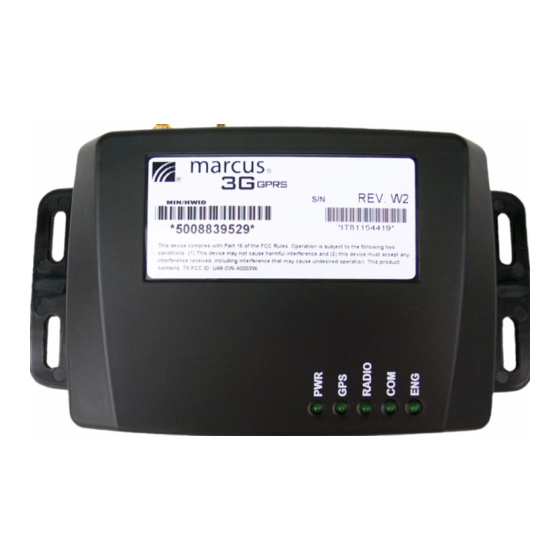
Appendix C: Description of Views Pictures and Diagram of the MARCUS® 3G Radio Top View with LEDs MARCUS® 3G Radio Module Top View MARCUS® 3G Radio Module USB: USB Connector Port SIM DOOR: SIM Tray PWR: Device is powered - GREEN Permanently ON - Device Functional - Permanently OFF - No Power or Device Nonfunctional GPS: GPS fix is valid... -
Page 19: Appendix C: Technical Specifications
MARCUS® 3G GPRS Device GPS Receiver FCC ID (UA80DW-0003W) Manufacturer - U-blox GPS Receiver Module ANTARIS® Manufacturer - Discrete Wireless, Inc. DW– A0003W2 L1 frequency, C/A code, 16 channel Processor: ARM® Core, Blackfin® DSP Accuracy: Position 2.5 m CEP Dimension: 1.375” H x 3.375 L x 4.75” W Start-up Times: •...
Need help?
Do you have a question about the MARCUS 3G GPRS and is the answer not in the manual?
Questions and answers