
Related Manuals for p5 Preliminary Opti Lite

Summary of Contents for p5 Preliminary Opti Lite
-
Page 1: Opti Lite
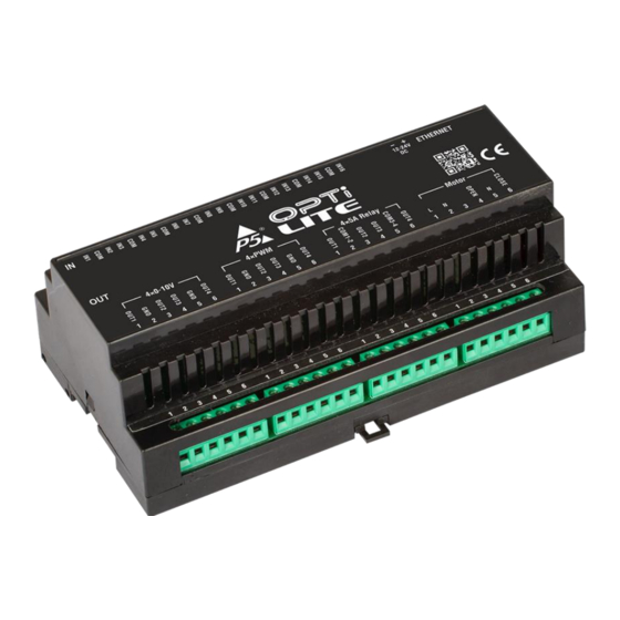
Opti Lite Installation and Operations Manual Preliminary rev 26.04.2023 Opti Lite Multifunction device Figure 1. Opti Lite module P a g e... -
Page 2: Table Of Contents
Opti Light is the ultimate way to approach multi-dwelling unit projects. OPTI Lite is basically a 4in1 FutureNow (the established product range by P5) with more power and resources. You no longer have to buy a different box for each function. -
Page 3: Installation
The OPTI Lite main board has 16 digital inputs and 4 slots for Output Boards. OPTI Lite comes with the Output Boards in place so you must specify the type of boards at the time of the order. INSTALLATION WARNING! This equipment shall be installed in a closed cabinet with no access to live parts. -
Page 4: Input Wiring Diagram
Input Wiring diagram Power 12 - 24V DC Inputs 16 and 15 in this example are connected to Common indicating how keypads with shared common can be used. Recommended wire types • Ethernet cable: Twisted pair, CAT5E or better. • Outputs: According to the load attached to the outputs (current and voltage ratings). -
Page 5: Output Modules
Output modules 2x16A This output module has two independent NO/NC relays. 2x16A in DCM mode This output module can control a DC motor with polarity change direction control. DCM mode should be selected on the System page. 4x5A relays There are 4 relays on this output 2 3 C board. -
Page 6: 4Xpwm Outputs
4xPWM outputs 4 channel PWM outputs for LED dimming. Multiple Power supplies can be used (12V-48V) Please note: All external power supplies used to power the LEDs must be connected to the GND terminal of this output module. 2x16A Bi-stable relays 2 Channel NO/NC relays They are latched in both positions and only use power to switch over. -
Page 7: Control Page
The Inputs section appears on all pages: All input states are shown, clicking on an input the action defined on the Trigger page will be executed. Control page: P a g e... -
Page 8: System Page
System Page Configuration of the Output modules 4xPWM Gamma Correction: To equalize brightness change for human eyes in the range of control slider movement. RGBW calculation: The module will calculate the brightness of the white LEDs based on the RGB values. Ch1 Ramp rate is also the ramp rate for RGB commands, including using the Color Picker. -
Page 9: System Settings Are Straight Forward
System settings P a g e... -
Page 10: Trigger Page
Trigger page Trigger settings • Triggers define the connection between the inputs and the outputs • Any input can control any outputs • Save to permanent storage must be used to save the changes 1. Input action 2. Output board 3. Channel & Action 4. - Page 11 12 – 24 VDC Input parameters Contact closure inputs Maximum resistance < 10 2x16A Output module Type 2 x SPDT NO, NC, dry contacts Max voltage within this 250V Output module Load (AC) max. 16A for resistive (cos(fi)=1) load max. 8A for inductive (cos(fi)=0.4) load Load (DC) max 16A@24V 4x5A Output module...
- Page 12 Package Content Warranty Opti Lite 2 years Quick Installation Guide REFERENCES Opti Lite discovery tool (Registration needed on www.p5automation.com) (Please email us at support@p5.hu to request the Communication Protocol Description) CONTACT DETAILS support@p5.hu http://p5.hu/index.php/support/contact-technical-support 12 | P a g e...
Need help?
Do you have a question about the Preliminary Opti Lite and is the answer not in the manual?
Questions and answers