
Related Manuals for p5 FNIP-8x16A.v4

Summary of Contents for p5 FNIP-8x16A.v4
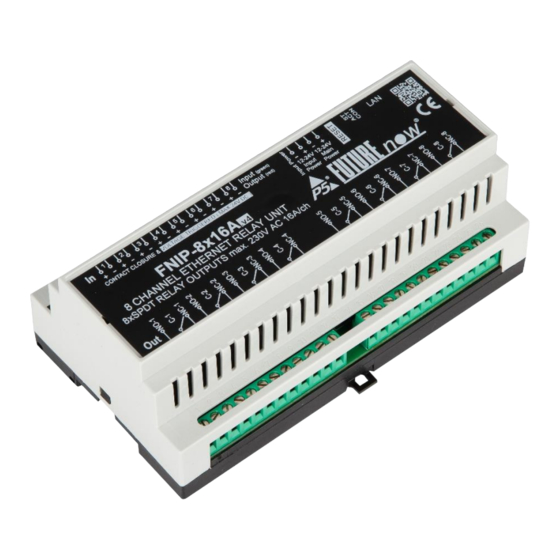
- Page 1 FutureNow FNIP-8x16A.v4 Installation and Operations Manual rev 25.05.2021 8 Channel Relay Switch with Local Inputs and IP communication /DIN Rail and Surface Mountable/ Figure 1. The FNIP-8x16A.v4 relay module P a g e...
-
Page 2: Table Of Contents
Table of Content INSTALLATION..............................3 Terminal connections ............................3 Wiring diagrams ..............................5 Outputs ................................6 Local Inputs ................................ 6 Status LED Indicators diagram ........................... 7 CONFIGURATION ..............................9 Configuration via the web interface ........................9 Once logged in, you will automatically be directed to the control page. you can see the details in the Operation section. -
Page 3: Installation
Each module has a wiring diagram on the front which can help the installer when connecting the modules at installation sites. See figure 2. The terminal connections of the FNIP-8x16A.v4 are listed in Table 1. Figure 2. FNIP-8x16A.v4 front view with terminal connectors... - Page 4 Output 6 N.C. Power for the Main Circuit + (12V – 24V DC) Output 7 N.O. Output 7 C. Output 7 N.C. Output 8 N.O. Output 8 C. Output 8 N.C. Table 1: FNIP-8x16A.v4 terminal connectors P a g e...
-
Page 5: Wiring Diagrams
Wiring diagrams External Power Voltage 12 - 24V DC Source 9 - 26V DC Power Input Wiring diagram 12 - 24V DC External Power Voltage 12 - 24V DC Source 9 - 26V DC Power 12 - 24V DC Input Main Power Power... -
Page 6: Outputs
The galvanic isolation of the inputs is only effective if a separate power supply is used for powering the inputs. The FNIP-8x16A.v4 has separate power input terminals (43 and 44) for this purpose. If you choose not to use the extra protection the isolated inputs offer, you can use the same power supply for both the main circuit and the inputs. -
Page 7: Status Led Indicators Diagram
Output status (red) Input Main Figure 4. The board layout of the FNIP-8x16A.v4 (top section) Figure 5. The actual picture of the FNIP-8x16A.v4 (top section) Input & Output status LEDs Each input/output has a dedicated status LED that illuminates green/red when the corresponding input/output is activated. - Page 8 Act LED - yellow The Act LED indicates that communication via Ethernet is in progress. St LED - red The status LED indicates that the boot loader of the module is active. This should only happen during firmware update. Please never disconnect power from the module while this LED is on! If this LED stays on after the firmware update, contact your dealer! P a g e...
-
Page 9: Configuration
CONFIGURATION Configuration can be done either via the built-in website or via TCP/IP connection. In the latter case the configuration interface the third-party controller provides is used. Configuration via the web interface Use the FNIP Network Discovery Utility software to find all FutureNow IP devices on your network. -
Page 10: Once Logged In, You Will Automatically Be Directed To The Control Page. You Can See The Details In The Operation Section
The default user has administrator rights and offer access to all settings and functions. Once logged in, you will automatically be directed to the control page. you can see the details in the Operation section. You can use the tabs on the top of the screen to navigate between the different control and configuration pages. -
Page 11: Users And User Rights
Figure 7. Network Configuration Page Users and user rights Three different users can be defined, each with three different user rights: admin, actor and observer. Admins have access to all functions, including control of the outputs, monitoring the status of the inputs and outputs and changing all the settings. Actors are allowed to control the outputs and monitor the status of the inputs and the outputs, but are not allowed to change any settings. - Page 12 Figure 8. User Configuration Page 12 | P a g e...
-
Page 13: Channel Settings
Channel settings On the Channel page the outputs and inputs can be renamed. Input modes can also be chosen here. The input mode determines the logical connection between the input and the output of the given channel. For details on possible input modes and how they work, see Operation via the local inputs section of this document. -
Page 14: Scenes
Scenes Scenes are predefined states of the outputs on the module. FutureNow Scenes are developed to provide group commands for FutureNow modules. Any input of any module in the group can trigger any outputs in the same group of modules. If a module receives a Scene Activation Command (SAC), the designated outputs will go to a pre-defined state. -
Page 15: Firmware Upgrade
On the Firmware page click browse and find the new firmware on your PC. The latest firmware versions are always downloadable from P5’s website. Then click Upload. The St LED turns on and stays on or blinks during firmware update. After uploading the new firmware –... -
Page 16: Operation
OPERATION Operation via the local inputs The inputs can be activated by shorting (or opening) the appropriate input terminal, or applying 9 – 24V voltage. Input modes The inputs are factory defaulted to toggle mode and can be changed via the web interface of the module or by TCP/IP commands. -
Page 17: Operation Via The Built-In Web Server
toggle the outputs. Please note that the position of the switch – similarly to three- way switches – will not determine the status of the output. 6. Scene on open mode If an input gets opened the scene assigned to the input on the channel configuration page will be executed. -
Page 18: Input Page
Input page: This page displays the logical status of the inputs. Figure 13. Input Page Please note: If an input is inverted, then the logical status is the opposite of the actual status displayed by the LED. Operation via TCP To achieve the easiest integration with most controllers used in home and commercial applications, the module can be controlled by raw TCP protocol using simple ASCII based commands. - Page 19 Neets • Home Assistant Software modules/plug-ins for controllers are either available or P5 will provide full assistance in creating them. Besides these special-purpose controllers, there have been many applications for embedded industrial PC boards, PCs and smartphones running Linux, Windows, Mac OS.
-
Page 20: Technical Specifications
TCP (simple ASCII TCP commands) Build-in web server Local inputs (Voltage triggered, or dry contact momentary switches) Input modes Toggle, monostable, input follow, independent iOS/Android app P5 iOS/Android apps Interoperability Drivers available for most systems Connectors Input Terminals 1.5mm² screw terminals Output Terminals 2.5mm²... - Page 21 Package Content Warranty FNIP-8x16A.v4 2 years Quick Installation Guide REFERENCES FNIP Discovery Tool FNIP Search Utility: (Registration needed on www.p5.hu) FNIP-8x16A TCP Communication Protocol Description (Please email us at support@p5.hu to request the Communication Protocol Description) CONTACT DETAILS support@p5.hu http://p5.hu/index.php/support/contact-technical-support...
Need help?
Do you have a question about the FNIP-8x16A.v4 and is the answer not in the manual?
Questions and answers