
Related Manuals for alora mood EMIKO

Summary of Contents for alora mood EMIKO
- Page 1 EMIKO CEILING FAN INSTRUCTION SHEET MODEL: CF523056 1.855.855.8926 | technicalsupport@aloralighting.com CANADA: 19054 28th Ave., - Surrey, BC V3Z 6M3 USA: 3035 E. Lone Mountain Rd. - Las Vegas, NV 89081 www.aloramood.com 20230505...
- Page 2 SAFETY RULES To reduce the risk of electric shock, ensure electricity The outlet box and support structure must be securely has been turned off at the circuit breaker or fuse box mounted and capable of reliably supporting a minimum before beginning. of 50 pounds.
- Page 3 CONTENTS • Safety • Fan Blade Installation • Tools Needed • Light Kit Installation • Package Contents • Fan Operation • Hardware Included • Care and Cleaning • Fan Assembly • Troubleshooting • Electrical Connections • Warranty Information TOOLS NEEDED •...
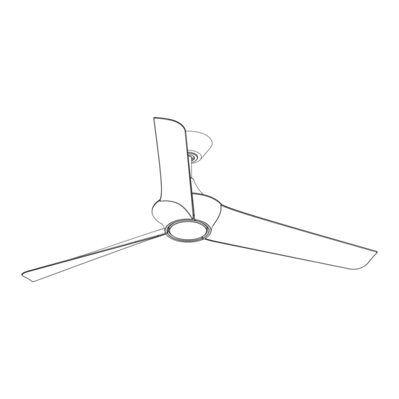
- Page 4 PACKAGE CONTENTS PART DESCRIPTION Mounting Bracket Canopy Canopy Screw Cover Hanger Ball/Downrod Assembly Coupling Cover Fan Motor Blade Blade Support Plate LED Light kit Assembly Receiver Remote Control Page 3 of 14...
- Page 5 PREPARING THE MOUNTING HARDWARE Outlet Box Mounting Options If there isn’t an existing UL Listed octagonal mounting box marked “Acceptable for Fan Support” follow the instructions below. (REMINDER: an electrical junction box for use with luminaires is not acceptable for this application) •...
- Page 6 PREPARING THE MOTOR Remove the cotter pin and clevis pin, and Cross pin loosen the two collar set screws from the motor collar. Set screw Hanger ball Take out the set screw located in the hanger Downrod Cotter pin ball, lower the hanger ball and remove the cross pin.
- Page 7 HANGING THE FAN WARNING: The tab in the ring must rest in the groove of the hanger ball/downrod assembly. Failure Groove Mounting to properly seat the tab in the groove could cause bracket damage to the wiring. Carefully lift the fan motor assembly up to the mounting bracket and seat the hanger ball/ downrod assembly in the mounting bracket socket.
- Page 8 ELECTRICAL CONNECTIONS WARNING: To avoid possible electrical shock, be sure BLK (AC IN) GROUND electricity is turned off at the main fuse box before WH (AC IN) installation. Outlet box NOTE: Control must be installed within 30 feet of fan. Ceiling WARNING: Check to see that all connections are tight, including ground, and that no bare wire is...
- Page 9 INSTALLING THE CANOPY WARNING: Make sure the tab on the mounting bracket properly sits in the groove in the hanger ball/downrod assembly before attaching the canopy to the mounting bracket by turning the Mounting bracket canopy until it drops into place. Canopy mounting screw Make sure connections are neatly tucked into...
- Page 10 INSTALLATION OF THE BLADES WARNING: To reduce the risk of personal injury, do not bend the blades while installing, balancing the blades, or cleaning the fan. Fasten blade to motor with provided blade support plates and screws. Repeat procedure for remaining blades. Make sure screws are TIGHT! Loose motor screws can contribute to unnecessary hum or wobble during operation.
- Page 11 OPERATION IMPORTANT: If you have two or more fans, please Light Button: follow steps below to control each fan independently. This button is to control light “ON/OFF” and Also follow steps below to re-pair the remote and “Dimmable” condition. the receiver when needed. SET code setting button: NOTE: The dip switch in the battery compartment Follow the below steps to set the remote control:...
- Page 12 OPERATION (CONTINUED) NOTE: The learning frequency function and self Over 80W protection: When the receiver calibration test will continue to retain the last set detects motor power consumption which is frequency and calibration set even when the AC greater than 80W, the receiver power will be power is shut off.
- Page 13 INSTALLING THE REMOTE CONTROL HOLDER Remove the remote control holder cover from Remote control the remote control holder. holder cover Screws Attach the remote control holder with the two remote control holder mounting screw provided. Replace the remote control holder cover into remote control holder.
- Page 14 TROUBLESHOOTING PROBLEM SOLUTION FAN WILL NOT START Check circuit fuses or breakers. Check wall control LED indicator light. If LED is not illuminated when pushing a button, it is not transmitting a signal. Please check battery, power to wall control/ circuit breaker and all electrical connections.
- Page 15 KUZCO GROUP CEILING FAN LIFETIME LIMITED WARRANTY Kuzco Group products are warranted against defects in materials and construction, subject to conditions and exclusions, for a period of two (2) years from the date of product shipment to the customer. Kuzco Group warrants the original owner that the motor in the fan will be free from defects for the lifetime of the fan.
- Page 16 FAN SLOPE CEILING ADAPTOR INSTALLATION SHEET MODEL: X-ADP 34 FAN 604.538.7162 604.538.7196 1.855.855.8926 | CANADA: 19054 28th Ave. - Surrey, BC V3Z 6M3 USA: 3035 E. Lone Mountain Rd. - Las Vegas, NV 89081 www.kuzcolighting.com 20230802...
- Page 17 X-ADP 34 FAN FAN SLOPE CEILING ADAPTOR ACCESSORY INSTALLATION SHEET WARNING: TO REDUCE THE RISK OF PERSONAL INJURY, USE ONLY WARNING: TO REDUCE THE RISK OF ELECTRIC SHOCK, ENSURE THE TWO STEEL SCREWS (AND LOCK WASHERS) PROVIDED WITH ELECTRICITY HAS BEEN TURNED OFF AT THE CIRCUIT BREAKER OR THE OUTLET BOX FOR MOUNTING TO THE OUTLET BOX.
- Page 18 FAN DOWNROD ACCESSORY INSTALLATION SHEET MODEL: X-RD34-06 FAN X-RD34-12 FAN X-RD34-18 FAN X-RD34-24 FAN X-RD34-36 FAN 1.855.855.8926 | 604.538.7162 604.538.7196 CANADA: 19054 28th Ave. - Surrey, BC V3Z 6M3 USA: 3035 E. Lone Mountain Rd. - Las Vegas, NV 89081 www.kuzcolighting.com 20230901...
- Page 19 X-RD34-06 FAN X-RD34-12 FAN X-RD34-18 FAN X-RD34-24 FAN FAN DOWNROD ACCESSORY X-RD34-36 FAN INSTALLATION SHEET WARNING: TO REDUCE THE RISK OF ELECTRIC WARNING: TO REDUCE THE RISK OF PERSONAL SHOCK, ENSURE ELECTRICITY HAS BEEN TURNED INJURY, USE ONLY THE TWO STEEL SCREWS (AND OFF AT THE CIRCUIT BREAKER OR FUSE BOX BEFORE LOCK WASHERS) PROVIDED WITH THE OUTLET BOX BEGINNING.
Need help?
Do you have a question about the EMIKO and is the answer not in the manual?
Questions and answers