
Related Manuals for EBS PX200NB


Summary of Contents for EBS PX200NB
- Page 1 2G/3G/4G COMMUNICATOR PX200NB Installation and programming manual Issue: Release date: 05.09.2022 Firmware version: 2.15.1 EBS Config 2.0 version: 1.5.03.017...
- Page 2 DECLARATION OF COMPLIANCE We, EBS Sp. z o.o., declare with full responsibility that the present product meets all requirements provided for in the Directive 2014/53/EU of European Parliament and Council dated 16 April 2014. The copy of the “Declaration of Compliance” can be found at www.ebssmart.com.
-
Page 3: Table Of Contents
3. Assembly and wiring ................9 3.1. PX200NB communicator ..............9 3.2. Input configuration ................. 11 3.3. Remote control configuration (only PX200NB-5R version) ...... 11 4. Quick start procedure ................13 5. Operation .................... 15 6. Configuration program ................16 6.1. Initial remarks ................16 6.2. - Page 4 Profiles and profile settings ........... 43 9.1.2. Servers ................... 44 9.1.3. Connection ................45 9.1.3.1. Test events period ............... 45 9.1.3.2. Primary server ..............45 9.1.3.3. Backup server ..............45 9.1.4. Connection stability ..............46 PX200NB – Manual Page 4 / 57...
- Page 5 DATA TRANSMISSION ..............54 12.4. RECEIVING OF DTMF DATA ............54 12.5. PROGRAMMING ................54 12.6. FIRMWARE UPDATING ..............55 12.7. SIM CARD ERROR ................ 55 12.8. SYSTEM ERROR ................56 13. Changelog .................... 57 PX200NB – Manual Page 5 / 57...
-
Page 6: Introduction
The device is basically purposed for data transmission from security systems installed in detached houses and in small business facilities. Additionally PX200NB communicator has got input for connection of an alarm control panel’s phone communicator. This provides for a cheap system of data transmission. -
Page 7: Functional And Technical Parameters
2. FUNCTIONAL AND TECHNICAL PARAMETERS GPRS, SMS, PSTN* – PX200NB-50; GPRS, LTE- FDD, SMS, PSTN* - PX200NB-Q30; GPRS, EDGE, Transmisson channels LTE-FDD, LTE-TDD, SMS, PSTN* - PX200NB- Q10; *transparent, PSTN dialer required in a CP Backup server YES (GPRS, SMS) - Page 8 13.5V / 160V (with EBS transformer) primary) Threshold of signaling low battery voltage Dimension PCB: 146 x 73 x 35 mm Working temperature -10ºC … +55ºC Working humidity 5% … 93% Standards PX200NB – Manual Page 8 / 57...
-
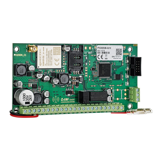
Page 9: Assembly And Wiring
3. ASSEMBLY AND WIRING 3.1. PX200NB COMMUNICATOR Fig. 1. Connecting the PX200NB communicator Connections of wires shall be made with due care to prevent any faults or dead shorts. Places of connections shall be protected against weather conditions. According to the figure 1. - Page 10 After careful connections examination a battery may be connected (to +ACU and GND terminals) and then power may be switched on for transformer and programming procedure of communicator may begin (See chapter 6. Configuration program). PX200NB – Manual Page 10 / 57...
-
Page 11: Input Configuration
Fig. 2. Examples of connecting sensors to the inputs in various configurations 3.3. REMOTE CONTROL CONFIGURATION (ONLY PX200NB-5R VERSION) The device in version PX200NB-5R provides 2 additional virtual inputs that can be triggered by radio communicators. The way of functioning should be configured by GPRS configurator software. Remote control programming procedure Press PROG (B) and hold. - Page 12 After the third STATUS LED flash, the communicator will enter the erasing mode. Press the PROG button again and wait to LED STATUS off. Release the button. Erasing of pre-programmed remotes will be confirmed by lighting up STATUS LED and PX200NB – Manual Page 12 / 57...
-
Page 13: Quick Start Procedure
Two phases comprise programming in this option: a) sending to communicator of main parameters (with SMS) that enable connection to communication server (OSM.Server system). b) full configuration of device with remote programming (EBS Config and OSM.Server). Quick start procedure: a) insert into device SIM card with PIN code 1111 or without PIN code. - Page 14 1111 █ SERVER=89.123.115.8 █ PORT=6780 █ APN=general.t-mobile.uk █ █ Where: █: space character PX200NB – Manual Page 14 / 57...
-
Page 15: Operation
Text message on events sent to private phone numbers may be edited. All programmable parameters are saved in memory and in case of voltage drop that are not lost. Supply of power starts the communicator with saved settings. PX200NB – Manual Page 15 / 57... -
Page 16: Configuration Program
6.3. SMARTPHONE TECHNICAL REQUIREMENTS EBS Config 2.0 is currently only available for Android smartphones. Android version at least 5.1 or newer is required for correct installation and operation of EBS Config 2.0 mobile application. 6.4. INSTALLATION If you have a SIM card with a pre-programmed PIN code other than 1111, you should first configure the device using the EBS Config 2.0 by entering the pre-... -
Page 17: General Menu
6.5.1. Opens a new set of parameters for the other kind of devices – control panels and transmitters. With this option, you can edit the configuration parameters of the proper device. For PX200NB: PX200NB – Manual Page 17 / 57... -
Page 18: Open
Additionally, the following parameters can be monitored in real time: Status of server connection, Status of DC power, The GSM/LTE network signal level, Status of the wired inputs, Status of the wired outputs, Arming mode. PX200NB – Manual Page 18 / 57... -
Page 19: Read Configuration
(use field “Device time and date”). By clicking “Send” button, you can start sending the defined data, with a message bar containing successful/failed sending information shown at the bottom of the app. PX200NB – Manual Page 19 / 57... -
Page 20: Events History
Firmware update 6.5.8. The device has a built-in bootloader, so that you can change the module software for the newer. In the window displayed, browse to the location of the file and press “Update”. PX200NB – Manual Page 20 / 57... -
Page 21: Restoring Factory Settings
The users and devices added to the communicators will not be deleted but their configuration will be deleted. Connection settings 6.5.10. Click on to display a window with the available connection methods shown: PX200NB – Manual Page 21 / 57... - Page 22 If the new ports have not been displayed automatically after connecting the programming device, press “Refresh ports”. When using the Bluetooth connection, the first step is to pair the programming device (SP-PROG-BT, MINI-PROG-BT) with the PC/smart phone. Select the correct PX200NB – Manual Page 22 / 57...
-
Page 23: Application Settings
The correct device is the one plugged into the communicator. Only after pairing the programming device with a PC an open port will be shown in EBS Config assigned for communication between the programming device and a PC. Application settings 6.5.11. -
Page 24: Programmable Parameters
Number of wired inputs/outputs. • 7.2. COMMUNICATOR (TRANSMITTER) SETTINGS After opening the tab, the main parameters of the device are shown for the first. Clicking on the “Advance” below, shows the remaining parameters. PX200NB – Manual Page 24 / 57... -
Page 25: Service Code
NOTE! If the code was not defined while programming the communicator, entering it during the first registration of the device in the EBS Security application will cause the code to be stored in the device. Subsequent change of the code can be done only via EBS Config 2.0. -
Page 26: Power Supply And Communication Stability
After clicking on this option, additional list will show, where you can set the time for exit. Partition inputs will be monitored when this configured time elapses after partition input had been armed. PX200NB – Manual Page 26 / 57... -
Page 27: Disarming Delay (Time For Entry)
If input is not assigned to any partition, it acts as 24 hours input – it is monitored regardless of partitions state. 7.4. INPUTS/OUTPUTS Communicators PX200NB have 9 inputs, two outputs. The "Input/Output" option allows to configure the communicator in accordance with the requirements of the user PX200NB –... -
Page 28: Wired Inputs
Violations with a slider for setting a lock for input after a specific number of violations (input state change) from 1 to 100, and Duration where you have to set duration time for lock of the input. PX200NB – Manual Page 28 / 57... -
Page 29: Wired Output
– connection follows for time defined by user. 7.4.2.2. Additional activation conditions In this section you can define conditions for activating of outputs. PX200NB – Manual Page 29 / 57... -
Page 30: Event Control
Telephone line (call initiation/termination, picking up/putting down the handset, dialing); • Transmitter status (service); • Communication with monitoring center (jamming, data transmission control, configuration change, time setting); • Informational (Clip, start of transmitter - communicator); PX200NB – Manual Page 30 / 57... -
Page 31: Sms Settings
In this section, a user may define the period for the device to transfer information in a text message. It is defined separately for: Tests sent to server periodically • Events sent to the server • PX200NB – Manual Page 31 / 57... -
Page 32: Limits
To add the rules, press . In the displayed window, you can enter up to 5 rules applying to transferring text message commands: PX200NB – Manual Page 32 / 57... -
Page 33: Custom Sms Messages
SMS messages that have been assigned to them. To do this, press and define the phone number in the window that appears, select the type of events to be sent and confirm then by clicking Add: PX200NB – Manual Page 33 / 57... -
Page 34: Status
In this section, each event in the list can be assigned a predefined unique SMS notification zone. When the event occurs, an SMS notification with the selected content will be sent to defined numbers will be sent an SMS notification with the selected content. PX200NB – Manual Page 34 / 57... -
Page 35: Rs232
If RS232 checkbox will not be enabled, data to the Event monitor will be sent on device’s serial port. With this setting, GD-PROG cable can be used to observe device state using EBS Config 2.0 PX200NB – Manual Page 35 / 57... -
Page 36: Buffering Flushing
The device is equipped with a PSTN phone line connector. It may be used to transmit data from an alarm control panel. Additionally communicator may collect information from the control panel using its a phone communicator, and next transmit them via PX200NB – Manual Page 36 / 57... -
Page 37: Phone Line Settings
GSM / LTE. Note: The communicator will simulate a telephone line in these cases: o A PSTN line is not connected o A PSTN line is connected but has not been activated. PX200NB – Manual Page 37 / 57... -
Page 38: Report Off-Hook Time Longer Than
7.7.1.4. Report off-hook time longer than This option is being used if in configuration “PSTN line – PX200NB – Alarm Control Panel” there are not other telecommunication devices. If such device will be connected and telephone number will be dialled (and a call will follow) after expiry defined time limit (counted since conclusion of last digit dialling) the communicator sends a message. -
Page 39: Monitoring Centre
For the purpose of maximum security of transmission, data is encrypted with AES key. This option may be used for GSM/LTE and SMS transmission. After selection of encrypted transmission you may use your own code (256 bits – signs 0-9 and A-F) or use default settings. PX200NB – Manual Page 39 / 57... -
Page 40: Events
This option allows for locking of sending of information on status of active inputs at power connection. Information on inputs will be sent to server after the first change from inactive to active status. PX200NB – Manual Page 40 / 57... -
Page 41: Events Modifier
Mobile network status, • Signal quality, • Used connection mode, • Power supply voltage of the communicator. Note: Using of the modifiers slightly increases the number of data sent over the GSM/LTE network. PX200NB – Manual Page 41 / 57... -
Page 42: Connection Channels
Additional tabs will be displayed after selecting communication channels: cellular network, Ethernet, SMS mode – depends on what mode was selected. 9.1. CELLULAR NETWORK If SIM card has been inserted into the SIM holder, the tab will look like this: PX200NB – Manual Page 42 / 57... -
Page 43: Mobile Network Operator Profile
Check via web browser; • Contact with the mobile network operator; • Best solution is to use functionalities of EBS Config 2.0 application, run communicator with the SIM card of the given mobile network operator, open PX200NB – Manual Page 43 / 57... -
Page 44: Servers
It is usually not required with public APNs. If you have a private APN, you should ask your provider for this parameter (you will need it to access the LTE/HSPA+ network). User's password PX200NB – Manual Page 44 / 57... -
Page 45: Connection
The rest of the procedure depends on the parameter: “Always try to connect to the primary server first”. If this option is enabled, the device will attempt to connect to the primary server. If it is disabled, the PX200NB – Manual Page 45 / 57... -
Page 46: Connection Stability
PIN code of the card matches the PIN code defined in the device. If the PIN codes are the same, the next step (using the IMSI code) verifies which operator the card is from. Next, it is verified whether a server phone number has been defined for the SIM PX200NB – Manual Page 46 / 57... -
Page 47: Profiles And Profile Settings
Contact with the mobile network operator; • Best solution is to use functionalities of EBS Config 2.0 application, run communicator with the SIM card of the given mobile network operator, open window ‘Device state’ (details in chapter 6.5.4 Device state... -
Page 48: Phone Number
In case of a loss of the GSM/LTE connection all information on upcoming events will be instantly sent by text message, even if the device have not switched to the Text message mode yet. PX200NB – Manual Page 48 / 57... -
Page 49: Device Programming
10. DEVICE PROGRAMMING Programming of device is possible with “EBS Config 2.0” configuration program described in chapter 5. To program the device establish connection with a device. Depending on connection mode there are two ways for programming. 10.1. LOCAL PROGRAMING... -
Page 50: Reprogramming Of Device
Save settings in memory of device. Saving course is displayed in special window. c) After saving completion close configuration wizard. d) The device is ready to transmit data according to new settings. PX200NB – Manual Page 50 / 57... -
Page 51: Receiving Of Sms Message
If APN address contain space sign put it with “”, e.g. “my apn”. UN=un APN user name for SIM 1 card. Parameter should be obtained from mobile network operator. If APN user PX200NB – Manual Page 51 / 57... - Page 52 Note: DESC, CMD, GETSTATUS, GETPARAM, GETCFG commands require separate SMS, so one command with only one SMS. Samples of commands and device reaction: Parameters setting: 1111█APN= general.t-mobile.uk█SERVER=89.112.43.78█PORT=6670█ SMS=500445566█SMSPERIOD=25 Parameters verification: Inquiry: 1111█GETCFG Answer: 89.112.43.78:6670,general.t-mobile.uk██, Inquiry: 1111█GETPARAM=SMS Answer: 500445566 PX200NB – Manual Page 52 / 57...
-
Page 53: Led Diodes Indication
GSM range is being indicated. LED Diodes Description DTMF ERROR OK STATUS OK (green) ERROR (red) GSM/LTE range = 8 Cellular network mode GSM/LTE range = 6 SMS mode PX200NB – Manual Page 53 / 57... -
Page 54: Data Transmission
LED Diode Signalling STATUS DTMF ERROR OK STATUS DTMF (HandShake) (KissOff) DTMF ERROR OK STATUS 6 digits of phone 16 digits ContactID 12.5. PROGRAMMING After detection of programming wire, diodes indicate programming. PX200NB – Manual Page 54 / 57... -
Page 55: Firmware Updating
(1/sec) Software updating Received firmware 10 sek decoding 12.7. SIM CARD ERROR In case of SIM card problems, device states this with OK and ERROR LEDs. Signalling LED diode DTMF ERROR OK STATUS PX200NB – Manual Page 55 / 57... -
Page 56: System Error
ERROR and mostly it means communication problem with modem or SIM card. Programming of device is possible with EBS Config configuration program described in chapter 6. To program the device establish connection with a device. Depending on connection mode there are two ways for programming. -
Page 57: Changelog
GPRS transmitters configurator on EBS Config 06.04.2022 / i1.11 Adding information about a new PX200NB-Q10 05.09.2022 / i2.0 Updating the chapter on the program Config (EBS Config 2.0); adding information on mobile network operator profiles and modifiers. PX200NB – Manual...
Need help?
Do you have a question about the PX200NB and is the answer not in the manual?
Questions and answers