Table of Contents
Advertisement
Available languages
Available languages
Quick Links
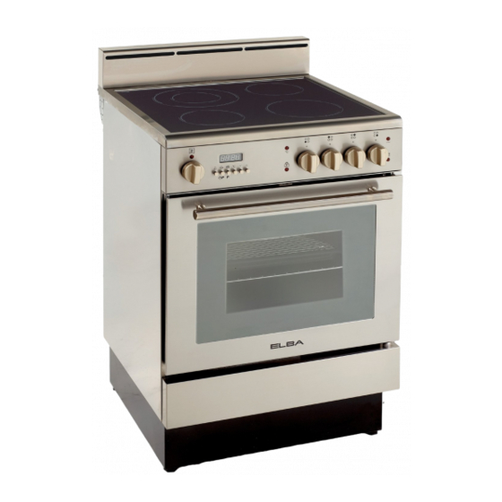
ELECTRIC RANGE
for residential use only
DE 2402 SC
• INSTALLATION INSTRUCTIONS
IMPORTANT - PLEASE READ AND FOLLOW
E N G L I S H
IMPORTANT - PLEASE READ AND FOLLOW
Before beginning, please read these instructions completely and carefully.
Do not remove permanently affixed labels, warnings, or plates from the product. This
may void the warranty.
Please observe all local and national codes and ordinances.
Please ensure that this product is properly grounded.
The installer should leave these instructions with the consumer who should retain
for local inspector's use and for future reference.
Electrical installation must be in accordance with the National Electrical Code,
ANIS/NFPA70 - latest edition and/or local codes.
IN CANADA: Electrical installation must be in accordance with the current CSA C22.1
Canadian Electrical Codes Part 1 and/or local codes.
This range is supplied with a protective film on
This film must be removed before installing/using the appliance.
FOR INSTALLER ONLY
E S P A Ñ O L
steel and aluminium parts.
Advertisement
Table of Contents

Related Manuals for Avanti DE 2402 SC


Summary of Contents for Avanti DE 2402 SC
- Page 1 ELECTRIC RANGE for residential use only DE 2402 SC • INSTALLATION INSTRUCTIONS IMPORTANT - PLEASE READ AND FOLLOW E N G L I S H E S P A Ñ O L IMPORTANT - PLEASE READ AND FOLLOW Before beginning, please read these instructions completely and carefully.
- Page 2 WARNING • ALL RANGES CAN TIP • INJURY TO PERSON COULD RESULT • INSTALL ANTI-TIP DEVICE PACKED WITH RANGE • SEE INSTALLATION INSTRUCTIONS...
-
Page 3: Installation Instructions
CAUTION: Range is heavy; use care in handling. service on the range. Replacement parts are available from factory authorized parts distributors. Contact the nearest AVANTI parts distributor in your area. Electrical Requirement Electrical installation should comply with national and local codes. -
Page 4: Installation
installation PROXIMITY TO SIDE CABINETS 1. This range may be installed directly adjacent to existing 36" (914 mm) high base cabinets. Range dimensions: • width: 23” 29/64 (596 mm) • depth: 23” 27/64 (595 mm) • height (without backguard): MIN 35” 5/8 (905 mm) - MAX 36” 13/32 (925 mm) •... -
Page 5: Assembling The Backguard
PROXIMITY TO SIDE CABINETS Fig. 6.3 Fig. 6.2 ASSEMBLING THE BACKGUARD It is mandatory to install the backguard • Assemble the backguard as shown in figure 6.4 and fix it by screwing the 3 screws “A”. Fig. 6.4... - Page 6 LEVELLING THE RANGE The range is equipped with 4 LEVELLING FEET and may be levelled by screwing or unscrewing the feet with a spanner (fig. 6.6). It is important to observe the prescriptions of figures 6.5a, 6.5b, 6.5c. Fig.6.5a Supplied with the range in a separate kit 0 mm + 8 mm...
-
Page 7: Electrical Connection
electrical connection ELECTRICAL REQUIREMENTS WARNING • This appliance must be properly installed and grounded by a qualified technician in accordance with the National Electrical Code ANSI/NFPA No.70 (latest edition) and TO AVOID ELECTRICAL SHOCK local electrical code requirements. IN CANADA: Electrical installation must be in HAZARD, BEFORE INSTALLING THE APPLIANCE, SWITCH POWER OFF AT accordance with the current CSA C22.1 Canadian Electrical Codes Part1 and/or local... - Page 8 3-Wire Flat Power Cord Installation Fig. 7.1 Screws (See Figures 7.1 and 7.2) 1. Remove the Terminal Block Access Plate on the back of the range by unscrewing the 4 fixing Screws. 2. Insert the Flat Power Cord through the Bracket; then tighten the Flat Power Cord by using the Strain Relief.
- Page 9 3-Wire Power Cord Installation Fig. 7.3 (See Figures 7.1, 7.3, 7.4 and 7.5) Bracket 1. Remove the Terminal Block Access Plate on the back of the Fixing Screws range by unscrewing the 4 fixing Screws (fig. 7.1). 2. Remove the Bracket and Strain Relief group by unscrewing the Bracket Fixing Screws (fig.
- Page 10 3-Wire Conduit Installation Fig. 7.7 (See Figures 7.1, 7.7, 7.8 and 7.9) Bracket 1. Remove the Terminal Block Access Plate on the back of the Fixing Screws range by unscrewing the 4 fixing Screws (fig. 7.1). 2. Remove the Bracket and Strain Relief group by unscrewing the Bracket Fixing Screws (7.7).
- Page 12 The manufacturer cannot be held responsible for possible inaccuracies due to printing or transcription errors in the present booklet. The manufacturer reserves the right to make all modifications to its products deemed necessary for manufacture or commercial reasons at any moment and without prior notice, without jeopardising the essential functional and safety characteristics of the appliances.
- Page 13 COCINA ELÉCTRICA para uso doméstico únicamente DE 2402 SC • INSTRUCCIONES DE FUNCIONAMIENTO PARA USUARIOS IMPORTANTE – LE ROGAMOS LEER Y RESPETAR LO SIGUIENTE E N G L I S H E S P A Ñ O L IMPORTANTE - LEER CUIDADOSAMENTE Antes de iniciar, lea cuidadosamente todas las instrucciones.
- Page 14 ADVERTENCIA • TODAS LAS COCINAS PUEDEN VOLCARSE • PUEDEN CAUSAR DAÑOS A PERSONAS • INSTALAR EL DISPOSITIVO ANTIVUELCO EMBALADO CON LA COCINA • CONSULTAR LAS INSTRUCCIONES PARA LA INSTALACIÓN...
-
Page 15: Instrucciones De Instalación
Puede localizar los recambios en distri- CUIDADO: Preste atención durante la manipulación. buidores de recambios autorizados. Póngase en contacto con el distribuidor de recambios AVANTI más cercano en su zona. Requisito Eléctrico La instalación eléctrica debe estar conforme con los códigos nacionales y locales. -
Page 16: Instalación
instalación PROXIMIDAD CON LOS ARMARIOS LATERALES 1. Puede instalar esta cocina directamente adycente con armarios de base con una altura de 36" (914 mm). Dimensiones de la cocina: • ancho: 23” 29/64 (596 mm) • profundidad: 23” 27/64 (595 mm) •... - Page 17 PROXIMIDAD A ARMARIOS LATERALES Fig. 6.3 Fig. 6.2 MONTAJE DE LA PLACA POSTERIOR Es obligatorio instalar la placa posterior • Ensamblar la placa posterior siguiendo las indicaciones de la figura 6.4 y fijarla enroscando los 3 tornillos “A”. Fig. 6.4...
- Page 18 NIVELANDO LA COCINA La cocina está equipada con 4 pies regulables y puede nivelarse enroscando o desen- roscando los pies con una llave (fig. 6.6). Es importante respetar las indicaciones de las figuras 6.5a, 6.5b, 6.5c. Fig.6.5a suministrado con la cocina en un kit separado 0 mm + 8 mm...
-
Page 19: Conexión Eléctrica
conexión eléctrica EXIGENCIAS ELÉCTRICAS WARNING • Un técnico cualificado debe instalar y disponer una puesta de tierra de forma ade- cuada para este aparato en conformidad con el "National Electrical Code ANSI/NFPA TO AVOID ELECTRICAL SHOCK No.70” - Última edición y según las exigencias de códigos eléctricos locales. HAZARD, BEFORE INSTALLING THE APPLIANCE, SWITCH POWER OFF AT EN CANADÁ: La instalación eléctrica se debe efectuar de acuerdo con el actual... - Page 20 Instalación del cable de alimentación Fig. 7.1 Tornillos de fijación plano de 3 hilos (Véanse las figuras 7.1 y 7.2) 1. Quite la placa de acceso del bloque de terminales en la parte trasera de la cocina desenroscando los 4 tornillos de fijación.
- Page 21 Instalación del cable de alimentación de 3 Fig. 7.3 hilos Tornillos (Véanse las figuras 7.1, 7.3, 7.4 y 7.5) de fijación del estribo 1. Quite la placa de acceso del bloque de terminales en la parte trasera de la cocina desenroscando los 4 tornillos de fijación (fig.
- Page 22 Instalación del conducto de 3 hilos Fig. 7.7 (véanse las figuras 7.1, 7.7, 7.8 y 7.9) Tornillos 1. Quite la placa de acceso del bloque de terminales en la de fijación del estribo parte trasera de la cocina desenroscando los 4 tornillos de fijación (fig.
- Page 24 El fabricante declina toda responsabilidad en caso de errores de impresión, transcripción del presente manual de instrucciones. El fabricante se reserva el derecho de aportar todas las modificaciones a sus productos que considere necesa- rias por razones de fabricación o comercialización, en cualquier momento, sin aviso previo, sin comprometer las medidas de seguridad y las características esenciales del funcionamiento.
Need help?
Do you have a question about the DE 2402 SC and is the answer not in the manual?
Questions and answers