Table of Contents
Advertisement
Quick Links
Advertisement
Table of Contents

Related Manuals for Arcteq AQ-S255


Summary of Contents for Arcteq AQ-S255
- Page 1 AQ-S255 Bay control device Instruction manual...
-
Page 2: Table Of Contents
3.2 Configuring user levels and their passwords................. 14 4 Functions unctions ...................................................... 16 4.1 Functions included in AQ-S255.................... 16 4.2 Measurements........................17 4.2.1 Current measurement and scaling ................17 4.2.2 Voltage measurement and scaling ................33 4.2.3 Voltage memory ......................45 4.2.4 Power and energy calculation .................. - Page 3 6 Connections and applic 6 Connections and applica a tion examples tion examples..................................280 6.1 Connections of AQ-S255....................280 6.2 Application example and its connections................282 6.3 Two-phase, three-wire ARON input connection ..............283 6.4 Trip circuit supervision (95) ....................284...
- Page 4 8.3 Tests and environmental ....................332 9 Or 9 Ordering inf dering informa ormation tion ..............................................334 10 Contact and r 10 Contact and re e f f er erence inf ence informa ormation tion....................................336 © Arcteq Relays Ltd IM00025...
- Page 5 Nothing contained in this document shall increase the liability or extend the warranty obligations of the manufacturer Arcteq Relays Ltd. The manufacturer expressly disclaims any and all liability for any damages and/or losses caused due to a failure to comply with the instructions contained herein or caused by persons who do not fulfil the aforementioned requirements.
-
Page 6: Document Inf
- Order codes revised. - Added double ST 100 Mbps Ethernet communication module and Double RJ45 10/100 Mbps Ethernet communication module descriptions Revision 2.02 Date 7.7.2020 Changes - A number of image descriptions improved. Revision 2.03 Date 27.8.2020 © Arcteq Relays Ltd IM00025... - Page 7 (powers, impedances, angles etc.). - Improvements to many drawings and formula images. - AQ-S255 Functions included list Added: CBFP. - Changed disturbance recorder maximum digital channel amount from 32 to 95. - Added residual current coarse and fine measurement data to disturbance recorder description.
- Page 8 - Added more descriptions to new IEC 61850 ed2 GOOSE parameters. - Added "Condition monitoring / CB wear" description to object description. - Added "User button" description. - Added logical device and logical node mode descriptions. Revision 2.09 Date 14.3.2023 © Arcteq Relays Ltd IM00025...
-
Page 9: Version 1 Revision Notes
A A Q Q -S255 -S255 1.2 Version 1 revision notes Instruction manual Version: 2.09 - Updated the Arcteq logo on the cover page and refined the manual's visual look. - Added the "Safety information" chapter and changed the notes throughout the document accordingly. -
Page 10: Abbreviations
CBFP – Circuit breaker failure protection CLPU – Cold load pick-up CPU – Central processing unit CT – Current transformer CTM – Current transformer module CTS – Current transformer supervision DG – Distributed generation DHCP – Dynamic Host Configuration Protocol © Arcteq Relays Ltd IM00025... - Page 11 RMS – Root mean square RSTP – Rapid Spanning Tree Protocol RTD – Resistance temperature detector RTU – Remote terminal unit SCADA – Supervisory control and data acquisition SG – Setting group SOTF – Switch-on-to-fault SW – Software © Arcteq Relays Ltd IM00025...
- Page 12 -S255 1 Document information Instruction manual 1.4 Abbreviations Version: 2.09 THD – Total harmonic distortion TRMS – True root mean square VT – Voltage transformer VTM – Voltage transformer module VTS – Voltage transformer supervision © Arcteq Relays Ltd IM00025...
-
Page 13: General
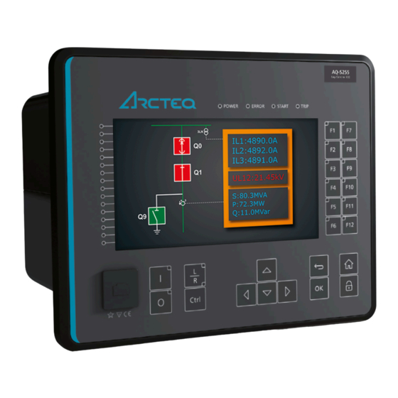
Version: 2.09 2 General The AQ-S255 bay control unit is a member of the AQ 250 product line. The hardware and software are modular: the hardware modules are assembled and configured according to the application's I/O requirements and the software determines the available functions. This manual describes the specific application of the AQ-S255 bay control device. -
Page 14: Device User Int Vice User Interface Erface
Home Home and the password activation buttons). 6. Twelve (12) freely configurable function buttons (F1…F12). Each button has a freely configurable LED (red, orange, green). 7. One (1) RJ-45 Ethernet port for device configuration. © Arcteq Relays Ltd IM00025... -
Page 15: Configuring User Levels And Their Passwords
The different user levels and their star indicators are as follows (also, see the image below for the HMI view): • Super user (***) • Configurator (**) • Operator (*) • User ( - ) © Arcteq Relays Ltd IM00025... - Page 16 Unlocking and locking a user level generates a time-stamped event to the event log in all AQ 250 series devices. NOTICE! TICE! Any user level with a password automatically locks itself after half an hour (30 minutes) of inactivity. © Arcteq Relays Ltd IM00025...
-
Page 17: Functions Unctions
Instruction manual Version: 2.09 4 Functions 4.1 Functions included in AQ-S255 The AQ-S255 bay control device includes the following functions as well as the number of stages in those functions. Table. 4.1 - 3. Protection functions of AQ-S255. Name ANSI... -
Page 18: Measurements
SEC: SEC: The secondary current, i.e. the current which the current transformer transforms according to its ratios. This current is measured by the device. NOM: NOM: The nominal primary current of the protected object. © Arcteq Relays Ltd IM00025... - Page 19 The following figure presents how CTs are connected to the device's measurement inputs. It also shows example CT ratings and nominal current of the load. Figure. 4.2.1 - 3. Connections. The following table presents the initial data of the connection. © Arcteq Relays Ltd IM00025...
- Page 20 (in this case they are the set primary and secondary currents of the CT). If the protected object's nominal current is chosen to be the basis for the per-unit scaling, the option "Object in p.u." is selected for the "Scale meas to In" setting (see the image below). © Arcteq Relays Ltd IM00025...
- Page 21 The ring core CT is connected to the CTM directly, which requires the use of sensitive residual current measurement settings: the "I02 CT" settings are set according to the ring core CT's ratings (10/1 A). © Arcteq Relays Ltd IM00025...
- Page 22 As the images above show, the scaling selection does not affect how primary and secondary currents are displayed (as actual values). The only effect is that the per-unit system in the device is scaled either to the CT nominal or to the object nominal, making the settings input straightforward. © Arcteq Relays Ltd IM00025...
- Page 23 The measured current amplitude does not match one of the measured Check the wiring connections between the injection device or the CTs and the device. phases./ The calculated I0 is measured even though it should not. © Arcteq Relays Ltd IM00025...
- Page 24 The following image presents the most common problems with phase polarity. Problems with phase polarity are easy to find because the vector diagram points towards the opposite polarity when a phase has been incorrectly connected. © Arcteq Relays Ltd IM00025...
- Page 25 If two phases are mixed together, the network rotation always follows the pattern IL1-IL3-IL2 and the measured negative sequence current is therefore always 1.00 (in. p.u.). © Arcteq Relays Ltd IM00025...
- Page 26 5 to connector 6, with the secondary currents' starpoint pointing towards the line. A feedback value; the calculated scaling factor that CT scaling is the ratio between the primary current and the factor P/S secondary current. © Arcteq Relays Ltd IM00025...
- Page 27 9 to connector A feedback value; the calculated scaling factor that is the scaling ratio between the primary current and the secondary factor P/S current. Measurements The following measurements are available in the measured current channels. © Arcteq Relays Ltd IM00025...
- Page 28 TRMS Sec") Table. 4.2.1 - 13. Phase angle measurements. Name Unit Range Step Description Phase angle The phase angle measurement from each of the three phase 0.00…360.00 0.01 ("Pha.angle current inputs. ILx") © Arcteq Relays Ltd IM00025...
- Page 29 0.00…300.00 0.01 calculated current channel I0. ("Sec.calc.I0") Secondary residual The secondary TRMS current (inc. harmonics up to 31 current I0x TRMS 0.00…300.00 0.01 measurement from the secondary residual current channel (Res.curr.I0x TRMS I01 or I02. Sec") © Arcteq Relays Ltd IM00025...
- Page 30 Secondary positive sequence current The secondary measurement from the calculated 0.00…300.00 0.01 ("Sec.Positive sequence positive sequence current. curr.") Secondary negative sequence current The secondary measurement from the calculated 0.00…300.00 0.01 ("Sec.Negative sequence negative sequence current. curr") © Arcteq Relays Ltd IM00025...
- Page 31 % 0.000...100.000 0.001 Power ratio THD voltage. Recognized by the IEEE. Current component measurements The current component measurements indicate the resistive (wattmetric cos[φ]) and reactive (varmetric sin[φ]) current values. These are calculated with the following formulas: © Arcteq Relays Ltd IM00025...
- Page 32 …100 000.00 from each of the phase current channels. Pri.") Primary reactive current ILx –100 000.00 The primary reactive current component measurement 0.01 ("ILx Reactive Current …100 000.00 from each of the phase current channels. Pri.") © Arcteq Relays Ltd IM00025...
- Page 33 ("I0x Resistive measurement from both of the residual current channels. Current Sec.") Secondary residual reactive current The secondary reactive current component –300.00…300.00 0.01 ("I0x Reactive measurement from both of the residual current channels. Current Sec.") © Arcteq Relays Ltd IM00025...
-
Page 34: Voltage Measurement And Scaling
VT ratings. In the figure below, three line-to-neutral voltages are connected along with the zero sequence voltage; therefore, the 3LN+U4 mode must be selected and the U4 channel must be set as U0. Other possible connections are presented later in this chapter. © Arcteq Relays Ltd IM00025... - Page 35 ( Protection → Voltage → [protection stage menu] → INFO ; see the image below). The number of available protection functions depends on the device type. Figure. 4.2.2 - 15. Selecting the measured magnitude. © Arcteq Relays Ltd IM00025...
- Page 36 • 2LL+U3+U4 (two line-to-line voltages and the U3 and the U4 channels can be used for synchrochecking, zero sequence voltage, or for both) The 3LN+U0 is the most common voltage measurement mode. See below for example connections of voltage line-to-line measurement (3LL on the left, 2LL on the right). © Arcteq Relays Ltd IM00025...
- Page 37 In the image below is an example of 2LL+U0+SS, that is, two line-to-line measurements with the zero sequence voltage and voltage from side 2 for Synchrocheck. Since U0 is available, line-to-neutral voltages can be calculated. Figure. 4.2.2 - 18. 2LL+U0+SS settings and connections. © Arcteq Relays Ltd IM00025...
- Page 38 The measured voltage amplitude does not match one of the measured phases./ Check the wiring connections between the injection device or the VTs and the device. The calculated U0 is measured even though it should not. © Arcteq Relays Ltd IM00025...
- Page 39 "U4 mode U0 or SS" has been set to 2: Open the "U0" mode. delta Voltage 0: Disabled Activates the voltage memory. The "Voltage memory" memory 1: Activated Disabled chapter describes the function in more detail. © Arcteq Relays Ltd IM00025...
- Page 40 VT scaling A feedback value; the scaling factor for the primary factor p.u. Pri voltage's per-unit value. VT scaling A feedback value; the scaling factor for the factor p.u. Sec secondary voltage's per-unit value. © Arcteq Relays Ltd IM00025...
- Page 41 The secondary RMS voltage measurement from each of the voltage Ux 0.00…500.00 0.01 voltage channels. ("Ux Volt sec") Secondary voltage Ux 0.00…500.00 0.01 The secondary TRMS voltage (inc. harmonics up to 31 TRMS measurement from each of the voltage channels. ("UxVolt TRMS sec") © Arcteq Relays Ltd IM00025...
- Page 42 ("Pos.seq.Volt.sec") Secondary negative 0.00…4 The secondary measurement from the calculated sequence voltage 0.01 800.00 negative sequence voltage. ("Neg.seq.Volt.sec") Secondary zero sequence 0.00…4 The secondary measurement from the calculated zero voltage 0.01 800.00 sequence voltage. ("Zero.seq.Volt.sec") © Arcteq Relays Ltd IM00025...
- Page 43 UL1 mag") System voltage magnitude 0.00…1 The primary RMS line-to-neutral UL2 voltage (measured or calculated). You 0.01 can also select the row where the unit for this is kV. ("System 000.00 volt UL2 mag") © Arcteq Relays Ltd IM00025...
- Page 44 UL23 0.00…360.00 0.01 The primary line-to-line angle UL23 (measured or calculated). ("System volt UL23 ang") System voltage angle UL31 0.00…360.00 0.01 The primary line-to-line angle UL23 (measured or calculated). ("System volt UL31 ang") © Arcteq Relays Ltd IM00025...
- Page 45 Defines how the harmonics are displayed: in p.u. values, as 1: Primary V display primary voltage values, or as secondary voltage values. 2: Secondary V Maximum 0.00…100 Displays the maximum harmonics value of the selected harmonics value 0.01 000.00 voltage input Ux. ("UxMaxH") © Arcteq Relays Ltd IM00025...
-
Page 46: Voltage Memory
2. At least one phase current must be above the set value for the "Measured current condition 3I>" parameter. This setting limit is optional. Figure. 4.2.3 - 21. Distance protection characteristics and directional overcurrent. © Arcteq Relays Ltd IM00025... - Page 47 Table. 4.2.3 - 38. Measurement inputs of the voltage memory function. Signal Description Time base IL1RMS RMS measurement of phase L1 (A) current IL2RMS RMS measurement of phase L2 (B) current IL3RMS RMS measurement of phase L3 (C) current RMS measurement of voltage U © Arcteq Relays Ltd IM00025...
- Page 48 When the "Forced CT f tracking" parameter is activated and voltages are gone, the frequency from the selected current-based reference channel 3 (the current from IL3) is used for current sampling. This eliminates any possible measurement errors in the fixed frequency mode. Figure. 4.2.3 - 23. Frequency reference channels. © Arcteq Relays Ltd IM00025...
-
Page 49: Power And Energy Calculation
The following equations apply for power calculations with the line-to-neutral mode and the line- to-line voltage mode (with U0 connected and measured): © Arcteq Relays Ltd IM00025... - Page 50 The direction of reactive power is divided into four quadrants. Reactive power may be inductive or capacitive on both forward and reverse directions. Reactive power quadrant can be indicated with Tan (φ) (tangent phi), which is calculated according the following formula: © Arcteq Relays Ltd IM00025...
- Page 51 (i.e. wiring errors, wrong measurement modes, faulty frequency settings, etc.). Settings Table. 4.2.4 - 40. Power and energy measurement settings Name Range Step Default Description 3ph active 0: Disabled Enables/disables the active energy energy 1: Enabled Disabled measurement. measurement © Arcteq Relays Ltd IM00025...
- Page 52 Reset energy calculators Resets the memory of the indivisual phase 0: - (per phase) 0: - energy calculator. Goes automatically back to 1: Reset ("Reset E per the "-" state after the reset is finished. phase") © Arcteq Relays Ltd IM00025...
- Page 53 Range Step Default Description DC 1…4 Pulse out OUT1…OUTx None selected The selection of the controlled physical outputs. Power measurements The following power calculations are available when the voltage and the current cards are available. © Arcteq Relays Ltd IM00025...
- Page 54 ("E 3ph M or k")" under the general "Power and energy measurement settings". Table. 4.2.4 - 45. Three-phase energy calculations. Name Range Step Description -999 999 995 Exported Active Energy (P) 904.00…999 999 0.01 The total amount of exported active energy. (kWh or MWh) 995 904.00 © Arcteq Relays Ltd IM00025...
- Page 55 0.01 -1x10 …1x10 Lx (kVarh or MVarh) active energy is exported. Imported (Q) while Export (P) The imported reactive energy of the phase while 0.01 -1x10 …1x10 Lx (kVarh or MVarh) active energy is exported. © Arcteq Relays Ltd IM00025...
- Page 56 = 2.5 A, 120.00° Name Value Name Value Name Value Name Value L1 (S) L1 (S) 4.08 MVA L2 (S) L2 (S) 6.15 MVA L3 (S) L3 (S) 9.77 MVA 3PH (S) H (S) 20.00 MVA © Arcteq Relays Ltd IM00025...
- Page 57 = 2.5 A, 0.00° = 100.00 V, -90.00° = 2.5 A, -120.00° = 2.5 A, 120.00° Name Values 3PH (S) 20.00 MVA 3PH (P) 17.32 MW 3PH (Q) 0.00 Mvar 3PH Tan 0.00 3PH Cos 0.87 © Arcteq Relays Ltd IM00025...
-
Page 58: Frequency Tracking And Scaling
FFT calculation always has a whole power cycle in the buffer. The measurement accuracy is further improved by Arcteq's patented calibration algorithms that calibrate the analog channels against eight (8) system frequency points for both magnitude and angle. - Page 59 The second reference source for frequency 2: CT2IL2 1: CT1IL2 reference 2 tracking. 3: VT1U2 4: VT2U2 0: None 1: CT1IL3 Frequency 2: CT2IL3 1: CT1IL3 The third reference source for frequency tracking. reference 3 3: VT1U3 4: VT2U3 © Arcteq Relays Ltd IM00025...
- Page 60 Alg f avg 0.000…75.000Hz 0.001Hz - tracked frequencies and U4 voltage channel samples. 0: One f measured System 1: Two f Displays the amount of frequencies that are measured measured measured. frequency 2: Three f measured © Arcteq Relays Ltd IM00025...
-
Page 61: General Menu
The order code identification of the unit. System phase rotating order at The selected system phase rotating order. Can be changed with parameter the moment "System phase rotating order". UTC time The UTC time value which the device's clock uses. © Arcteq Relays Ltd IM00025... - Page 62 If set to 0 s, this feature is not in use. 0…3600s timeout When the device is in sleep mode pressing any of the buttons on the front panel of the device will wake the display. © Arcteq Relays Ltd IM00025...
- Page 63 Signals set to this point can be used for resetting latched signals. An alternative to Reset latches using the "Back" button on the front panel of the device. Ph.Rotating Logic control Signals set to this point can be used for switching the expected phase rotating 0=A-B-C, 1=A-C-B order. © Arcteq Relays Ltd IM00025...
-
Page 64: Protection Functions
1 ms. The function also provides a resettable cumulative counters for RETRIP, CBFP, CBFP START and BLOCKED events. The following figure presents a simplified function block diagram of the circuit breaker failure protection function. © Arcteq Relays Ltd IM00025... - Page 65 START or TRIP event. General settings The following general settings define the general behavior of the function. These settings are static i.e. it is not possible to change them by editing the setting group. © Arcteq Relays Ltd IM00025...
- Page 66 Selects the residual current monitoring source, which can be 0: Not I0Input 1: I01 either from the two separate residual measurements (I01 and I02) or in use 2: I02 from the phase current's calculated residual current. 3: I0Calc © Arcteq Relays Ltd IM00025...
- Page 67 The relay's Info page displays useful, real-time information on the state of the protection function. It is accessed either through the relay's HMI display, or through the setting tool software when it is connected to the relay and its Live Edit mode is active. © Arcteq Relays Ltd IM00025...
- Page 68 TRetr setting parameter will 1: Yes not be available. Retrip Retrip start the timer. This setting defines how long the starting time 0.000…1800.000s 0.005s 0.100s condition has to last before a RETRIP signal is activated. delay © Arcteq Relays Ltd IM00025...
- Page 69 The following figures present some typical cases of the CBFP function. Trip, Retrip and CBFP in the device configuration Figure. 4.4.1 - 28. Wiring diagram when Trip, Retrip and CBFP are configured to the device. © Arcteq Relays Ltd IM00025...
- Page 70 CBFP signal to the incomer breaker. If the primary protection function clears the fault, both counters (RETRIP and CBFP) are reset as soon as the measured current is below the threshold settings. © Arcteq Relays Ltd IM00025...
- Page 71 (RETRIP and CBFP) are reset as soon as the measured current is below the threshold settings or the tripping signal is reset. This configuration allows the CBFP to be controlled with current-based functions alone, and other function trips can be excluded from the CBFP functionality. © Arcteq Relays Ltd IM00025...
- Page 72 This configuration allows the CBFP to be controlled with current-based functions alone, with added security from current monitoring. Other function trips can also be included in the CBFP functionality. © Arcteq Relays Ltd IM00025...
- Page 73 Probably the most common application is when the device's trip output controls the circuit breaker trip coil, while one dedicated CBFP contact controls the CBFP function. Below are a few operational cases regarding the various applications and settings of the CBFP function. © Arcteq Relays Ltd IM00025...
- Page 74 CBFP signal is sent to the incomer breaker. If the primary protection function clears the fault, the counter for CBFP resets as soon as the measured current is below the threshold settings. © Arcteq Relays Ltd IM00025...
- Page 75 The time delay counter for CBFP is reset as soon as the measured current is below the threshold settings or the tripping signal is reset. This configuration allows the CBFP to be controlled by current-based functions alone, and other function trips can be excluded from the CBFP functionality. © Arcteq Relays Ltd IM00025...
- Page 76 This configuration allows the CBFP to be controlled by current-based functions alone, with added security from current monitoring. Other function trips can also be included to the CBFP functionality. © Arcteq Relays Ltd IM00025...
- Page 77 A A Q Q -S255 -S255 4.4 Protection functions Instruction manual Version: 2.09 Device configuration as a dedicated CBFP unit Figure. 4.4.1 - 36. Wiring diagram when the device is configured as a dedicated CBFP unit. © Arcteq Relays Ltd IM00025...
- Page 78 ON, OFF, or both. The events triggered by the function are recorded with a time stamp and with process data values. Table. 4.4.1 - 59. Event messages. Event block name Event names CBF1 Start ON CBF1 Start OFF © Arcteq Relays Ltd IM00025...
-
Page 79: Resistance Temperature Detectors (Rtd)
(2) separate alarms from one selected input. The user can set alarms and measurements to be either in degrees Celsius or Fahrenheit. The following figure shows the principal structure of the resistance temperature detection function. © Arcteq Relays Ltd IM00025... - Page 80 Table. 4.4.2 - 62. Function settings for Channel x (Sx). Name Range Step Default Description 0: No Enables/disables the selecion of sensor S1...S16 enable 0: No 1: Yes measurements and alarms. © Arcteq Relays Ltd IM00025...
- Page 81 Sets the value for Alarm 2. The alarm is activated if the measurement goes S1...S16 Alarm2 -101.0…2000.0deg 0.1deg 0.0deg above or below this setting mode (depends on the selected mode in "Sx Alarm2 >/<"). © Arcteq Relays Ltd IM00025...
- Page 82 S3 Alarm1 OFF RTD1 S3 Alarm2 ON RTD1 S3 Alarm2 OFF RTD1 S4 Alarm1 ON RTD1 S4 Alarm1 OFF RTD1 S4 Alarm2 ON RTD1 S4 Alarm2 OFF RTD1 S5 Alarm1 ON RTD1 S5 Alarm1 OFF © Arcteq Relays Ltd IM00025...
- Page 83 S11 Alarm1 ON RTD1 S11 Alarm1 OFF RTD1 S11 Alarm2 ON RTD1 S11 Alarm2 OFF RTD1 S12 Alarm1 ON RTD1 S12 Alarm1 OFF RTD1 S12 Alarm2 ON RTD1 S12 Alarm2 OFF RTD1 S13 Alarm1 ON © Arcteq Relays Ltd IM00025...
- Page 84 S4 Meas Invalid RTD2 S5 Meas Ok RTD2 S5 Meas Invalid RTD2 S6 Meas Ok RTD2 S6 Meas Invalid RTD2 S7 Meas Ok RTD2 S7 Meas Invalid RTD2 S8 Meas Ok RTD2 S8 Meas Invalid © Arcteq Relays Ltd IM00025...
-
Page 85: Programmable Stage (Pgx>/<; 99)
If a stage is not active the PSx>/< condition parameter will merely display “Disabled”. The function's outputs are START, TRIP and BLOCKED signals. The programmable stage function uses a total of eight (8) separate setting groups which can be selected from one common source. © Arcteq Relays Ltd IM00025... - Page 86 General menu. 3: Blocked 0: One magnitude comp 1: Two Defines how many measurement magnitudes are used by the PSx >/< Measurement setting magnitude stage. comp 2: Three magnitude comp © Arcteq Relays Ltd IM00025...
- Page 87 -5 000 000...5 PSx MagnitudeX multiplier multiplication). See section "Magnitude multiplier" for more 000 000 information. Analog values The numerous analog signals have been divided into categories to help the user find the desired value. © Arcteq Relays Ltd IM00025...
- Page 88 I01 primary current of a current-resistive component I01CapP I01 primary current of a current-capacitive component I01ResS I01 secondary current of a current-resistive component I01CapS I01 secondary current of a current-capacitive component I02ResP I02 primary current of a current-resistive component © Arcteq Relays Ltd IM00025...
- Page 89 Positive sequence voltage angle (degrees) U2 neg.seq.V Ang Negative sequence voltage angle (degrees) Table. 4.4.3 - 68. Power measurements Name Description S3PH Three-phase apparent power S (kVA) P3PH Three-phase active power P (kW) Q3PH Three-phase reactive power Q (kvar) © Arcteq Relays Ltd IM00025...
- Page 90 Positive Impedance Z primary (Ω) ZSeqSec Positive Impedance Z secondary (Ω) ZSeqAngle Positive Impedance Z angle Table. 4.4.3 - 71. Conductances, susceptances and admittances (L1, L2, L3) Name Description GLxPri Conductance G L1, L2, L3 primary (mS) © Arcteq Relays Ltd IM00025...
- Page 91 Transformer thermal temperature RTD meas 1…16 RTD measurement channels 1…16 Ext RTD meas 1…8 External RTD measurement channels 1…8 (ADAM) mA input 7,8,15,16 mA input channels 7, 8, 15, 16 ASC 1…4 Analog scaled curves 1…4 © Arcteq Relays Ltd IM00025...
- Page 92 -5 000 000...5 000 The ratio between measured magnitude and the pick-up MagSet1 at the setting. moment PSx >/< MeasMag2/ -5 000 000...5 000 The ratio between measured magnitude and the pick-up MagSet2 at the setting. moment © Arcteq Relays Ltd IM00025...
- Page 93 The pick-up activation of the function is not directly equal to the START signal generation of the function. The START signal is allowed if the blocking condition is not active. Comparator modes When setting the comparators, the user must first choose a comparator mode. © Arcteq Relays Ltd IM00025...
- Page 94 The variables the user can set are binary signals from the system. The blocking signal needs to reach the device minimum of 5 ms before the set operating delay has passed in order for the blocking to activate in time. © Arcteq Relays Ltd IM00025...
- Page 95 PGS1 PS4 >/< Start ON PGS1 PS4 >/< Start OFF PGS1 PS4 >/< Trip ON PGS1 PS4 >/< Trip OFF PGS1 PS4 >/< Block ON PGS1 PS4 >/< Block OFF PGS1 PS5 >/< Start ON © Arcteq Relays Ltd IM00025...
- Page 96 PGS1 PS8 >/< Block OFF PGS1 PS9 >/< Start ON PGS1 PS9 >/< Start OFF PGS1 PS9 >/< Trip ON PGS1 PS9 >/< Trip OFF PGS1 PS9 >/< Block ON PGS1 PS9 >/< Block OFF © Arcteq Relays Ltd IM00025...
-
Page 97: Control Functions
This control model is commonly called bus regulation. Other uses for voltage control are, for example, reactive power control and optimization of the transmission lines. © Arcteq Relays Ltd IM00025... - Page 98 The control settings include the operating mode selection ("Auto" or "Manual") as well as the settings for the maximum and minimum control pulse lengths for the used output contacts. Additionally, the settings include the setting for the minimum instant operation wait time between pulses. © Arcteq Relays Ltd IM00025...
- Page 99 Tap position indication mA input Tap steps total (Raise voltage steps + lower voltage steps) 18 steps Tap center (Nominal voltage position) 9 step Tap step effect 1.67 % mA input low range 4 mA © Arcteq Relays Ltd IM00025...
- Page 100 These basic settings define the control area where the AVR must operate. Either Channel 1 or 2 can be used to connect a mA input to an option card (see the image below). © Arcteq Relays Ltd IM00025...
- Page 101 4 Functions A A Q Q -S255 -S255 4.5 Control functions Instruction manual Version: 2.09 Figure. 4.5.1 - 40. Connecting mA input to option card. © Arcteq Relays Ltd IM00025...
- Page 102 If this is the case, this can be switched with the “Tap position indication” parameter, as shown in the image below. Figure. 4.5.1 - 42. Switching the tap position indication. Correcting non-linear mA tap position indication with current scaling © Arcteq Relays Ltd IM00025...
- Page 103 Figure. 4.5.1 - 43. Example of Scaled input setting. External mA input There is an alternative to using an RTD & mA card: one can also use an external mA unit (ADAM-4016) which connects to the RS-485 port. Binary coded inputs © Arcteq Relays Ltd IM00025...
- Page 104 Control → Control functions → Voltage regulator → IO → Input signal control . Up to five digital inputs can be set for BCD coding, and up to 18 positions can be indicated with BCD coding (see the image below). © Arcteq Relays Ltd IM00025...
- Page 105 Instead of mA measurement, RTD resistance is also an applicable option. To use RTD measurement the position indication needs to be scaled in Measurement → AI (mA, DI volt) scaling (see the image below). Figure. 4.5.1 - 44. Example scaling for tap position indication with RTD measurement. © Arcteq Relays Ltd IM00025...
- Page 106 Therefore, the minimum voltage window size can be calculated as follows: © Arcteq Relays Ltd IM00025...
- Page 107 Eventually a stable voltage may be found but the next tap change request will cause similar fluctuation and the cycle begins again. Figure. 4.5.1 - 47. Tight voltage window (window reached but voltage near the limit). © Arcteq Relays Ltd IM00025...
- Page 108 However, the voltage stays within the second window limits. Only when a second tap change is applied does the voltage drop within the limits of the first voltage window. © Arcteq Relays Ltd IM00025...
- Page 109 For example, if U >>/<<< time delay has been set to 40 seconds and the measured voltage difference from the set target is 4 %, using the formula above the operating time can be determined to be 10 seconds (40s / 4) © Arcteq Relays Ltd IM00025...
- Page 110 Figure. 4.5.1 - 50. Inverse operating time characteristics for the second voltage window (U>>/<< window The inverse operating time controls the voltage back to the set target window: the bigger the deviation (dU [%]) is, the smaller the operating time to get the voltage within the target window. © Arcteq Relays Ltd IM00025...
- Page 111 (U>>> Instant setting). After this level is reached, the time characteristics of the corresponding window calculate the consecutive time delays until the desired target window is reached. © Arcteq Relays Ltd IM00025...
- Page 112 10 % by local standards and the tap effect for the transformer is 1.67 %, the pick-up for the instant low function should be set to 8.33 % (10 % – 1.67 %). © Arcteq Relays Ltd IM00025...
- Page 113 (see the image below). This can occur in various power-off situations, such as when there is a heavy short-circuit fault in the feeding network side, or when the tap drifts towads the maximum voltage. © Arcteq Relays Ltd IM00025...
- Page 114 Table. 4.5.1 - 79. Measurement inputs of the automatic voltage regulator function. Signal Description Time base UL12 System Phase-to-phase system voltage UL12 UL23 System Phase-to-phase system voltage UL23 UL31 System Phase-to-phase system voltage UL31 © Arcteq Relays Ltd IM00025...
- Page 115 When opened displays the internal than U<< Vreg settings condition information about the settings. If the value 5: U>>> set too differs from 0, the settings are not correct. 6: U<<< set too high 7: VT selection not © Arcteq Relays Ltd IM00025...
- Page 116 Displays the set instant stage (compared to U>>> (instant) setting 0.00…140.00% 0.01% the nominal 100 % level). Displays the set upper limit of the second U>> setting 0.00…140.00% 0.01% window (compared to the nominal 100 % level). © Arcteq Relays Ltd IM00025...
- Page 117 Sets the maximum time the tap 0.000…1800.000s 0.005s 2.000s pulse length control's output contact can be closed. Min control Sets the minimum time the tap control's 0.000…1800.000s 0.005s 2.000s pulse length output contact must be closed. © Arcteq Relays Ltd IM00025...
- Page 118 This setting is only visible when "Scaled signal 4: Scaling curve 1 1 (mA) input" is the selected input mode. (position) 5: Scaling curve 2 (position) 6: Scaling curve 3 (position) 7: Scaling curve 4 (position) © Arcteq Relays Ltd IM00025...
- Page 119 "Binary coded inputs" is the selected input mode. Displays the mA input measurement value mA input now at the moment. (from the 0.000…20.000mA 0.001mA - This setting is visible, when any of the mA measurement) inputs is selected. © Arcteq Relays Ltd IM00025...
- Page 120 Sets the "voltage high" limit for the low-set voltage U> window. 0.10…30.00%U 0.01%U 0.88%U setting This setting is only visible, when the "U>/< window in (+UTGT) use" parameter is activated. © Arcteq Relays Ltd IM00025...
- Page 121 (- blocked. UTGT) Internal 0: Not in use 0: Not in Selects whether or not the internal overcurrent 1: In use detection blocks the AVR operation. blocking © Arcteq Relays Ltd IM00025...
- Page 122 AVR outputs Indicates that the output contact control is blocked, and that the actual output signals and blocked events are not given to the tap changer. © Arcteq Relays Ltd IM00025...
- Page 123 "From library", and then select one of the control button icons. Next, choose which logical input this button controls, and make sure that the two images in the item are following the status of the correct logical input (see the image below). © Arcteq Relays Ltd IM00025...
- Page 124 Tap Lower command OFF VRG1 Block operation ON VRG1 Block Operation OFF VRG1 Block Output commands ON VRG1 Block Output commands OFF VRG1 Low voltage blocking ON VRG1 Low voltage blocking OFF VRG1 Overcurrent blocking ON © Arcteq Relays Ltd IM00025...
- Page 125 Control Date and time Event Voltage now Tap now Used SG volt mode 0: Auto dd.mm.yyyy Event Voltage at the Tap location Target Setting hh:mm:ss.mss name moment of event value voltage group 1...8 active Manual © Arcteq Relays Ltd IM00025...
-
Page 126: Setting Group Selection
If a static activation signal is given for two setting groups, the setting group with higher priority will be active. If setting groups are controlled by pulses, the setting group activated by pulse will stay active until another setting groups receives and activation signal. © Arcteq Relays Ltd IM00025... - Page 127 This setting has to be active before the setting group can be changed group change Disabled remotely or from a local HMI. This parameter overrides the local control of Enabled the setting groups and it remains on until the user disables it. © Arcteq Relays Ltd IM00025...
- Page 128 The selection of Setting group 7 ("SG7"). Has the second lowest priority input in setting group control. group Can be controlled with pulses or static signals. If static signal control is applied, only SG8 requests will not be processed. © Arcteq Relays Ltd IM00025...
- Page 129 The status of the Petersen coil controls whether Setting group 1 is active. If the coil is disconnected, Setting group 2 is active. This way, if the wire is broken for some reason, the setting group is always controlled to SG2. © Arcteq Relays Ltd IM00025...
- Page 130 A A Q Q -S255 -S255 4 Functions Instruction manual 4.5 Control functions Version: 2.09 Figure. 4.5.2 - 58. Setting group control – two-wire connection from Petersen coil status. © Arcteq Relays Ltd IM00025...
- Page 131 The application-controlled setting group change can also be applied entirely from the relay's internal logics. For example, the setting group change can be based on the cold load pick-up function (see the image below). © Arcteq Relays Ltd IM00025...
- Page 132 The function does not have a register. Table. 4.5.2 - 91. Event messages. Event block name Event names SG2 Enabled SG2 Disabled SG3 Enabled SG3 Disabled SG4 Enabled SG4 Disabled © Arcteq Relays Ltd IM00025...
- Page 133 Remote Change SG Request ON Remote Change SG Request OFF Local Change SG Request ON Local Change SG Request OFF Force Change SG ON Force Change SG OFF SG Request Fail Not configured SG ON © Arcteq Relays Ltd IM00025...
-
Page 134: Object Control And Monitoring
Manual remote control can be done through one of the various communication protocols available (Modbus, IEC101/103/104 etc.). The function supports the modes "Direct control" and "Select before execute" while controlled remotely. Automatic controlling can be done with functions like auto-reclosing function (ANSI 79). © Arcteq Relays Ltd IM00025... - Page 135 The following parameters help the user to define the object. The operation of the function varies based on these settings and the selected object type. The selected object type determines how much control is needed and which setting parameters are required to meet those needs. © Arcteq Relays Ltd IM00025...
- Page 136 Displays the status of breaker. Intermediate is displayed when 1: Open Breaker neither of the status signals (open or close) are active. Bad status 2: Closed status is displayed when both status signals (open and close) are active. 3: Bad © Arcteq Relays Ltd IM00025...
- Page 137 Displays the number of failed "Close" requests. 0…2 –1 failed Clear 0: - Clears the request statistics, setting them back to zero (0). 0: - statistics 1: Clear Automatically returns to "-" after the clearing is finished. © Arcteq Relays Ltd IM00025...
- Page 138 Objectx Open command The physical "Open" command pulse to the device's output ("Objectx Open relay. Command") OUT1…OUTx Objectx Close command The physical "Close" command pulse to the device's output ("Objectx Close relay. Command") © Arcteq Relays Ltd IM00025...
- Page 139 The remote Open command from a physical digital Open control input input (e.g. RTU). Objectx Application The Close command from the application. Can be any Close logical signal. Objectx Application The Close command from the application. Can be any Open logical signal. © Arcteq Relays Ltd IM00025...
- Page 140 Figure. 4.5.3 - 62. Example of an interlock application. In order for the blocking signal to be received on time, it has to reach the function 5 ms before the control command. © Arcteq Relays Ltd IM00025...
- Page 141 RMS measurement of phase L2 (B) current IL3RMS RMS measurement of phase L3 (C) current Condition monitoring parameters can be found from Control → Objects → Object X → APP CONTR → Condition Monitoring . © Arcteq Relays Ltd IM00025...
- Page 142 Condition Alarm 2 Enable Enables Alarm 2. 1: Enabled Disabled Condition Alarm 2 when When the amount of operations left is less than value 0...200 000 operations less than set here, Alarm 2 will activate. © Arcteq Relays Ltd IM00025...
- Page 143 Close Command On OBJ1...OBJ10 Close Command Off OBJ1...OBJ10 Open Blocked On OBJ1...OBJ10 Open Blocked Off OBJ1...OBJ10 Close Blocked On OBJ1...OBJ10 Close Blocked Off OBJ1...OBJ10 Object Ready OBJ1...OBJ10 Object Not Ready OBJ1...OBJ10 Sync Ok OBJ1...OBJ10 Sync Not Ok © Arcteq Relays Ltd IM00025...
- Page 144 The cause of an "Open" command's failure. Close fail The cause of a "Close" command's failure. Open command The source of an "Open" command. Close command The source of an "Open" command. General status The general status of the function. © Arcteq Relays Ltd IM00025...
-
Page 145: Indicator Object Monitoring
Close input A link to a physical digital input. The monitored indicator's signal selected by the user ("Ind.X CLOSE status. "1" refers to the active "Close" state of the monitored Close indicator. (SWx) Status In") © Arcteq Relays Ltd IM00025... -
Page 146: Auto-Recloser (79)
Alternatively, the function can be set to initiate the final trip, locking the feeder closing. The decision between a single-shot and a multi-shot auto-recloser depends on the following: protection type, switchgear, circuit breaker, stability requirements, network type, consumer loads as well as local utility knowledge and network practices. © Arcteq Relays Ltd IM00025... - Page 147 (especially in rural areas) that there are multiple forest areas the line runs through between the consumer connections. In longer lines in sparsely populated areas it is possible to isolate areas of the overhead line by dividing it up with disconnectors (at least in branches). © Arcteq Relays Ltd IM00025...
- Page 148 • from Trip with two shots (high-speed fails, time-delayed succeeds) • from Trip with two shots (high-speed succeeds) • from Start with two shots (both fail) • from Start with two shots (high-speed fails, time-delayed succeeds) © Arcteq Relays Ltd IM00025...
- Page 149 Therefore, the auto-recloser function only monitors the status of the directional earth fault stage's tripping before initiating requests and shots. © Arcteq Relays Ltd IM00025...
- Page 150 A "Close" command is dropped after the breaker's "Closed" indication is received and the auto-recloser function starts calculating S S ho hot2 t2 R R eclaim T eclaim Time ime. © Arcteq Relays Ltd IM00025...
- Page 151 Figure. 4.5.5 - 69. Settings for I0dir> with two shots. This type of sequence (i.e. two shots required to clear the fault) represents 10...15 % of all faults that occur in MV overhead line networks. © Arcteq Relays Ltd IM00025...
- Page 152 9. The circuit breaker is closed and since the fault has been cleared, no pick-ups are detected. The "Close" command is dropped after the breaker's "Closed" indication is received and the auto- recloser function starts calculating S S ho hot2 t2 R R eclaim T eclaim Time ime. © Arcteq Relays Ltd IM00025...
- Page 153 This type of sequence (i.e. the first shot clears the fault) represents 75...85 % of all faults that occur in MV overhead line networks. Figure. 4.5.5 - 72. Signal status graph of the transient earth fault auto-recloser cycle. © Arcteq Relays Ltd IM00025...
- Page 154 The protection's main operating time settings should be longer than the values set to the auto-recloser function; this way the state changes work properly with this function. © Arcteq Relays Ltd IM00025...
- Page 155 Running Running, S S ho hot2 Running t2 Running and AR1 AR1 R R equest equested ed signals. The function enters the AR L AR Lock-out ock-out state to prevent any further requests for reclosing. © Arcteq Relays Ltd IM00025...
- Page 156 S S ho hot1 Star t1 Start T t Time ime. This activates the S S ho hot 1 Running Running signal eventhough the auto-recloser function is not yet running. © Arcteq Relays Ltd IM00025...
- Page 157 However, in this example the fault is cleared by the high-speed shot. Figure. 4.5.5 - 77. Settings for I> with two shots. This type of sequence (i.e. the first shot clears the fault) represents 75...85 % of all faults that occur in MV overhead line networks. © Arcteq Relays Ltd IM00025...
- Page 158 AR Reclaim is not used at all after a successful recloser cycle. 7. The AR R AR Reclaim eclaim time is exceeded and the function is set to "Ready" to wait for the next request. © Arcteq Relays Ltd IM00025...
- Page 159 This means that the time set to the "ARx Shot action time" parameter is a cumulative counter of time allowed before deciding whether a shot is failed or successful. © Arcteq Relays Ltd IM00025...
- Page 160 The behavior of the function can be changed even during sequences that are based on programmed reclosing schemes and on active requests. The following figure presents a simplified function block diagram of the auto-recloser function. © Arcteq Relays Ltd IM00025...
- Page 161 Enables or disables the auto-recloser function with any binary signal selected by the AR On/ signal in the user. The parameter "Use AR On/Off signals" defines whether this input signal is in device use or not. © Arcteq Relays Ltd IM00025...
- Page 162 "Use AR On/Off signals" is set to "Yes" and the input of the AR On/Off is inactive. AR In The signal "AR In progress" is activated and displayed when the function has opened the breaker progress and is calculating the time towards closing it. © Arcteq Relays Ltd IM00025...
- Page 163 No new successful sequence will be started while this signal is active, instead the function goes into the locked mode. sequence © Arcteq Relays Ltd IM00025...
- Page 164 0: Yes On/Off 1: No "No" the auto-recloser is always in use. If set to "Yes" binary signal set to 1: No signals "AR ON/OFF" has to be active for the auto-recloser to be enabled. © Arcteq Relays Ltd IM00025...
- Page 165 When the function is counting down towards any action, this parameter AR Timer 0...1800.00s displays how much time is left until the action is executed. The "Timer value active" setting displays what is the action when this timer reaches zero. © Arcteq Relays Ltd IM00025...
- Page 166 0.000…1800.000s 0.005s 10.000s request is applied during this time, the auto- reclaim time recloser enters the locked state to prevent further reclosing attempts. This selection can be changed via the device's setting group selection in real time. © Arcteq Relays Ltd IM00025...
- Page 167 ARx Shot 0.000…1800.000s 0.0005s 0.000s 0.000s reclaim time starts calculating. If the process reclaim time is interrupted by a new reclosing request, the function continues to the next shot. © Arcteq Relays Ltd IM00025...
- Page 168 The auto-recloser function's shot settings are grouped into corresponding rows to make the setting of each shot straightforward. From the settings the user can see how the reclosing cycle is executed by each request, which functions initiate requests, and which shots and requests are in use. © Arcteq Relays Ltd IM00025...
- Page 169 The user can enable timers to be displayed in the MIMIC view. Enable the AR timer value at Tools → Events and logs → Set alarm events (see the image below). The timer displays the reclaim time and the dead time delay. © Arcteq Relays Ltd IM00025...
- Page 170 Object failure, AR locked Shot failed AR cycle ends due to a discrimination request AR Shot clear Object "Close" request Object "Open" request Inhibit condition ON Inhibit condition OFF Locking condition ON Locking condition OFF Reserved © Arcteq Relays Ltd IM00025...
- Page 171 Shot 5 Execute ON Shot 5 Execute OFF Seqeunce finished, the Final trip armed Final trip executed Lock-out time ON Lock-out time OFF General reclaim time ON General reclaim time OFF Shot start time ON © Arcteq Relays Ltd IM00025...
- Page 172 AR Status: AR is ready, AR is not running, AR2 Requested, Executing Shot 1 hh:mm:ss.mss AR Timers: No timers running 0.000 s AR Status: AR is ready, AR is not running, Start time counting, AR2 Requested, Executing dd.mm.yyyy Shot 1 hh:mm:ss.mss AR Timers: Start Delay 0.000 s © Arcteq Relays Ltd IM00025...
- Page 173 AR1 Shot start time OFF dd.mm.yyyy hh:mm:ss.mss 4083 AR1 Dead time ON dd.mm.yyyy hh:mm:ss.mss 2963 OBJ1 Status change OFF dd.mm.yyyy hh:mm:ss.mss 4044 AR1 Object "Close" request dd.mm.yyyy hh:mm:ss.mss 2957 OBJ1 Close request ON dd.mm.yyyy hh:mm:ss.mss 2958 OBJ1 Close Fail © Arcteq Relays Ltd IM00025...
- Page 174 • AR started The counters are cumulative and they update automatically according to the operations of the auto- recloser function. They can be found in the Statistics tab at Control → Auto-recloser → Registers . © Arcteq Relays Ltd IM00025...
-
Page 175: Synchrocheck (Δv/Δa/Δf; 25)
The seven images below present three different example connections and four example applications of the synchrocheck function. Figure. 4.5.6 - 82. Example connection of the synchrocheck function (3LN+U4 mode, SYN1 in use, UL1 as reference voltage). © Arcteq Relays Ltd IM00025... - Page 176 Figure. 4.5.6 - 83. Example connection of the synchrocheck function (2LL+U0+U4 mode, SYN1 in use, UL12 as reference voltage). Figure. 4.5.6 - 84. Example connection of the synchrocheck function (2LL+U3+U4 mode, SYN3 in use, UL12 as reference voltage). © Arcteq Relays Ltd IM00025...
- Page 177 4.5 Control functions Instruction manual Version: 2.09 Figure. 4.5.6 - 85. Example application (synchrocheck over one breaker, with 3LL and 3LN VT connections). Figure. 4.5.6 - 86. Example application (synchrocheck over one breaker, with 2LL VT connection). © Arcteq Relays Ltd IM00025...
- Page 178 A A Q Q -S255 -S255 4 Functions Instruction manual 4.5 Control functions Version: 2.09 Figure. 4.5.6 - 87. Example application (synchrocheck over two breakers, with 2LL VT connection). © Arcteq Relays Ltd IM00025...
- Page 179 "live" or a "dead" state. The parameter SYNx U conditions is used to determine the conditions (in addition to the three aspects) which are required for the systems to be considered synchronized. The image below shows the different states the systems can be in. © Arcteq Relays Ltd IM00025...
- Page 180 4.5 Control functions Version: 2.09 Figure. 4.5.6 - 89. System states. The following figures present simplified function block diagrams of the synchrocheck function. Figure. 4.5.6 - 90. Simplified function block diagram of the SYN1 and SYN2 function. © Arcteq Relays Ltd IM00025...
- Page 181 The relay's Info page displays useful, real-time information on the state of the protection function. It is accessed either through the relay's HMI display, or through the setting tool software when it is connected to the relay and its Live Edit mode is active. © Arcteq Relays Ltd IM00025...
- Page 182 If the blocking signal is active when the SYN OK activates, a BLOCKED signal is generated and the function does not process the situation further. If the SYN OK function has been activated before the blocking signal, it resets. © Arcteq Relays Ltd IM00025...
- Page 183 - 3LN+U4(SS) SYN1 V 0: Not 3: UL31 - 2LL+U3(U0)+U4(SS) Reference in use 4: UL1 - 2LL+U3(SS)+U4(U0) 5: UL2 Reference options 0...3 available: 6: UL3 - 3LL+U4(SS) - 2LL+U3(Not in use)+U4(SS) - 2LL+U3(SS)+U4(Not in use) © Arcteq Relays Ltd IM00025...
- Page 184 4: LL & DL 0: LL conditions 5: LL & DD only L = Live 6: LL & LD & DL D = Dead 7: LL & LD & DD 8: LL & DL & DD 9: Bypass © Arcteq Relays Ltd IM00025...
- Page 185 SYN1 Volt diff out of setting SYN1 SYN1 Angle diff Ok SYN1 SYN1 Angle diff out of setting SYN1 SYN1 Frequency diff Ok SYN1 SYN1 Frequency diff out of setting SYN1 SYN2 Blocked ON SYN1 SYN2 Blocked OFF © Arcteq Relays Ltd IM00025...
- Page 186 SYN3 Angle diff out of setting SYN1 SYN3 Frequency diff Ok SYN1 SYN3 Frequency diff out of setting SYN1 SYN1 Switch ON SYN1 SYN1 Switch OFF SYN1 SYN2 Switch ON SYN1 SYN2 Switch OFF SYN1 SYN3 Switch ON © Arcteq Relays Ltd IM00025...
-
Page 187: Milliampere Output Control
• good for travelling long distances, as current does not degrade over long connections like voltage does • less sensitive to background electrical noise • detects a fault in the system incredibly easily since 4 mA is equal to 0 % output. © Arcteq Relays Ltd IM00025... - Page 188 The second input point in the mA output 0.001 …10 value 2 control curve. Scaled The mA output value when the measured value mA output 0.0000…24.0000mA 0.0001mA 0mA is equal to or greater than Input value 2. value 2 © Arcteq Relays Ltd IM00025...
- Page 189 Displays the input value of the selected mA 0.001 …10 Magnitude now output channel at that moment. mA Out Channel Displays the output value of the selected mA 0.0000…24.0000mA 0.0001mA Outputs now output channel at that moment. © Arcteq Relays Ltd IM00025...
-
Page 190: Programmable Control Switch
ON, OFF, or both. The function offers five (5) independent switches. Table. 4.5.8 - 123. Event messages. Event block name Event names Switch 1 ON Switch 1 OFF Switch 2 ON Switch 2 OFF Switch 3 ON Switch 3 OFF Switch 4 ON © Arcteq Relays Ltd IM00025... -
Page 191: User Buttons
Range Step Default Description Analog input 0: Disabled Enables and disables the input. scaling 1: Activated Disabled Scaling curve 0: Disabled Enables and disables the scaling curve and 1...4 1: Activated Disabled the input measurement. © Arcteq Relays Ltd IM00025... - Page 192 The signal can be assigned directly to an output relay or to an LED in the I/O matrix. The "Out of range" signal is activated, when the measured signal falls below the set input minimum limit, or when it exceeds the input maximum limit. © Arcteq Relays Ltd IM00025...
-
Page 193: Logical Outputs
64 logical outputs are available. The figure below presents a logic output example where a signal from the circuit breaker failure protection function controls the digital output relay number 5 ("OUT5") when the circuit breaker's cart status is "In". © Arcteq Relays Ltd IM00025... -
Page 194: Logical Inputs
AQ-200 unit or to give direct control commands. Logical inputs can be controlled with a virtual switch built in the mimic and from a SCADA system. Logical inputs are volatile signals: their status will always return to "0" when the AQ-200 device is rebooted. 32 logical inputs are available. © Arcteq Relays Ltd IM00025... - Page 195 Logical input descriptions Logical inputs can be given a description. The user defined description are displayed in most of the menus: • logic editor • matrix • block settings • event history • disturbance recordings • etc. © Arcteq Relays Ltd IM00025...
-
Page 196: Monitoring Functions
The function uses a total of eight (8) separate setting groups which can be selected from one common source. The operational logic consists of the following: © Arcteq Relays Ltd IM00025... - Page 197 The time stamp resolution is 1 ms. The function also provides a resettable cumulative counter for the CTS ALARM and BLOCKED events. The following figure presents a simplified function block diagram of the current transformer supervision function. © Arcteq Relays Ltd IM00025...
- Page 198 Table. 4.6.1 - 128. Measured inputs of the CTS function. Signal Description Time base IL1RMS RMS measurement of phase L1 (A) current IL2RMS RMS measurement of phase L2 (B) current IL3RMS RMS measurement of phase L3 (C) current © Arcteq Relays Ltd IM00025...
- Page 199 0: Add Defines the polarity of residual current channel connection. Subtract 0: - Compensate natural When activated while the line is energized, the currently present 0: - unbalance calculated residual current is compensated to 0. Comp © Arcteq Relays Ltd IM00025...
- Page 200 The relay's Info page displays useful, real-time information on the state of the protection function. It is accessed either through the relay's HMI display, or through the setting tool software when it is connected to the relay and its Live Edit mode is active. © Arcteq Relays Ltd IM00025...
- Page 201 "General properties of a protection function" and its section "Operating time characteristics for trip and reset". Typical cases of current transformer supervision The following nine examples present some typical cases of the current transformer supervision and their setting effects. © Arcteq Relays Ltd IM00025...
- Page 202 Figure. 4.6.1 - 99. Secondary circuit fault in phase L1 wiring. When a fault is detected and all conditions are met, the CTS timer starts counting. If the situation continues until the set time has passed, the function issues an alarm. © Arcteq Relays Ltd IM00025...
- Page 203 If any of the phases exceed the I high limit setting, the operation of the function is not activated. This behavior is applied to short-circuits and earth faults even when the fault current exceeds the I high limit setting. © Arcteq Relays Ltd IM00025...
- Page 204 Figure. 4.6.1 - 103. Normal situation, residual current also measured. When the residual condition is added with the "I0 input selection", the sum of the current and the residual current are compared against each other to verify the wiring condition. © Arcteq Relays Ltd IM00025...
- Page 205 Figure. 4.6.1 - 105. Broken primary phase current wiring. In this example, all other condition are met except the residual difference. That is now 0 × I , which indicates a primary side fault. © Arcteq Relays Ltd IM00025...
- Page 206 The function registers its operation into the last twelve (12) time-stamped registers; this information is available for all provided instances separately. The register of the function records the ON event process data for ACTIVATED, BLOCKED, etc. The table below presents the structure of the function's register content. © Arcteq Relays Ltd IM00025...
-
Page 207: Voltage Transformer Supervision (60)
1 ms. The function also provides a resettable cumulative counter for the START, ALARM BUS, ALARM LINE and BLOCKED events. Figure. 4.6.2 - 107. Secondary circuit fault in phase L1 wiring. The following figure presents a simplified function block diagram of the voltage transformer supervision function. © Arcteq Relays Ltd IM00025... - Page 208 RMS measurement of voltage U RMS measurement of voltage U RMS measurement of voltage U RMS measurement of voltage U Positive sequence voltage Negative sequence voltage Zero sequence voltage Angle of U voltage Angle of U voltage © Arcteq Relays Ltd IM00025...
- Page 209 Table. 4.6.2 - 136. Pick-up settings. Name Range Step Default Description Voltage If one the measured voltages is below low pickup value 0.05…0.50×U 0.01×U 0.05×U and two of the measured voltages exceed high detect pickup value the function's pick-up activates. © Arcteq Relays Ltd IM00025...
- Page 210 1: On Displays the mode of VTS block. 2: Blocked 3: Test This parameter is visible only when Allow setting of individual LN behaviour 4: Test/Blocked LN mode is enabled in General menu. 5: Off © Arcteq Relays Ltd IM00025...
- Page 211 ALARM ACTIVATED and BLOCKED signals. The user can select which event messages are stored in the main event buffer: ON, OFF, or both. The events triggered by the function are recorded with a time stamp and with process data values. © Arcteq Relays Ltd IM00025...
-
Page 212: Circuit Breaker Wear Monitoring
The circuit breaker wear function is used for monitoring the circuit breaker's lifetime and its maintenance needs caused by interrupting currents and mechanical wear. The function uses the circuit breaker's manufacturer-supplied data for the breaker operating cycles in relation to the interrupted current magnitudes. © Arcteq Relays Ltd IM00025... - Page 213 ALARM 2 events. The function can also monitor the operations left for each phase. The following figure presents a simplified function block diagram of the circuit breaker wear function. Figure. 4.6.3 - 110. Simplified function block diagram of the circuit breaker wear function. © Arcteq Relays Ltd IM00025...
- Page 214 The number of interrupting life operations at the nominal 0…200 000 50 000 current (Close - Open). Operations The number of interrupting life operations at the rated breaking 0…200 000 current (Open). Current 1 0…100.00kA 0.01kA 1kA The rated normal current (RMS). © Arcteq Relays Ltd IM00025...
- Page 215 Let us examine the settings, using a low-duty vacuum circuit breaker as an example. The image below presents the technical specifications provided by the manufacturer, with the data relevant to our settings highlighted in red: © Arcteq Relays Ltd IM00025...
- Page 216 0.80 kA Operation 1 30 000 operations Current 2 16.00 kA Operations 2 100 operations Enable Alarm 1 1: Enabled Alarm 1 Set 1000 operations Enable Alarm 2 1: Enabled Alarm 2 Set 100 operations © Arcteq Relays Ltd IM00025...
- Page 217 The user can select which event messages are stored in the main event buffer: ON, OFF, or both. The events triggered by the function are recorded with a time stamp and with process data values. Table. 4.6.3 - 145. Event messages. Event block name Event names CBW1 CBWEAR1 Triggered © Arcteq Relays Ltd IM00025...
-
Page 218: Current Total Harmonic Distortion (Thd)
Figure. 4.6.4 - 111. THD calculation formulas. While both of these formulas exist, the power ratio ( THD ) is recognized by the IEEE, and the amplitude ratio ( THD ) is recognized by the IEC. © Arcteq Relays Ltd IM00025... - Page 219 32 components from each measured current channel. From these measurements the function calculates either the amplitude ratio or the power ratio. A -20 ms averaged value of the selected magnitude is used for pre-fault data registering. © Arcteq Relays Ltd IM00025...
- Page 220 (in single, dual or all phases), it triggers the pick-up operation of the function. Table. 4.6.4 - 149. Pick-up settings. Name Range Step Default Description Enable phase 0: Enabled Enables and disables the THD alarm function from phase 1: Disabled Enabled currents. alarm © Arcteq Relays Ltd IM00025...
- Page 221 If the START function has been activated before the blocking signal, it resets and the release time characteristics are processed similarly to when the pick- up signal is reset. © Arcteq Relays Ltd IM00025...
- Page 222 THD1 THD Start I01 OFF THD1 THD Start I02 ON THD1 THD Start I02 OFF THD1 THD Alarm Phase ON THD1 THD Alarm Phase OFF THD1 THD Alarm I01 ON THD1 THD Alarm I01 OFF © Arcteq Relays Ltd IM00025...
-
Page 223: Voltage Total Harmonic Distortion (Thd)
The blocking signal and the setting group selection control the operating characteristics of the function during normal operation, i.e. the user or user-defined logic can change function parameters while the function is running. This only applies if the alarming is activated. © Arcteq Relays Ltd IM00025... - Page 224 Table. 4.6.5 - 154. Measurement inputs of the total harmonic distortion monitor function. Signal Description Time base UL1FFT FFT measurement of phase L1 (A) voltage UL2FFT FFT measurement of phase L2 (B) voltage UL3FFT FFT measurement of phase L3 (C) voltage © Arcteq Relays Ltd IM00025...
- Page 225 The relay's Info page displays useful, real-time information on the state of the protection function. It is accessed either through the relay's HMI display, or through the setting tool software when it is connected to the relay and its Live Edit mode is active. © Arcteq Relays Ltd IM00025...
- Page 226 BLOCKED signals. The user can select which event messages are stored in the main event buffer: ON, OFF, or both. The events triggered by the function are recorded with a time stamp and with process data values. © Arcteq Relays Ltd IM00025...
-
Page 227: Fault Locator (21Fl)
Function block uses analog current and voltage measurements and calculated phase-to-phase or phase-to-ground loop impedances. Table. 4.6.6 - 161. Measurement inputs of the 21FL function. Signals Description Time base VT1 U1, U2, U3 The line-to-neutral or line-to-line voltages of the first voltage transformer module. 5ms © Arcteq Relays Ltd IM00025... - Page 228 IL2, IL3 XL23 XL23 IL1, IL3 XL31 XL31 No trigger No trigger No trigger If no current measurement requirements are fulfilled when the function receives a triggering signal, the function will not record impedance at all. © Arcteq Relays Ltd IM00025...
-
Page 229: Disturbance Recorder (Dr)
The maximum sample rate of the recorder's analog channels is 64 samples per cycle. The recorder also supports 95 digital channels simultaneously with the twenty (20) measured analog channels. Maximum capacity of recordings is 100. © Arcteq Relays Ltd IM00025... - Page 230 F tracked 2 Tracked frequency of reference 2 F tracked 3 Tracked frequency of reference 3 ISup Current measurement module voltage supply supervision (CT card 1) ISup'' Current measurement module voltage supply supervision (CT card 2) © Arcteq Relays Ltd IM00025...
- Page 231 Pha.curr.ILx TRMS Pri ILx (IL1, IL2, IL3) IL2, IL3) Phase angle ILx (IL1, Positive/Negative/Zero sequence Pha.angle ILx Pos./Neg./Zero seq.curr. IL2, IL3) current Phase current ILx (IL1, Sec.Pos./Neg./Zero Secondary positive/negative/zero Pha.curr.ILx IL2, IL3) seq.curr. sequence current © Arcteq Relays Ltd IM00025...
- Page 232 System volt ULx mag(kV) ULx in kilovolts (U1, U2, U3, U4) Secondary Ux voltage Angle of the system voltage ULx Ux Volt TRMS sec TRMS (U1, U2, U3, System volt ULx ang (U1, U2, U3, U4) © Arcteq Relays Ltd IM00025...
- Page 233 ILx (IL1, IL2, Current Pri. Current Sec. current I0x (I01, I02) IL3) Power, GYB, frequency Lx power factor (L1, Lx PF Curve x Input Input of Curve x (1, 2, 3, 4) L2, L3) © Arcteq Relays Ltd IM00025...
- Page 234 Enable f based functions frequency-based protection component (Pri) component I01 functions are enabled. Table. 4.6.7 - 169. Digital recording channels – Binary signals. Signal Description Signal Description Digital input 1...11 Timer x Output Output of Timer 1...10 © Arcteq Relays Ltd IM00025...
- Page 235 "Estimating the maximum length of total recording time". Table. 4.6.7 - 170. Recorder control settings. Name Range Step Default Description Recorder 0: Enabled Enables and disables the disturbance recorder function. enabled 1: Disabled Enabled © Arcteq Relays Ltd IM00025...
- Page 236 Selects the trigger input(s). Clicking the "Edit" button brings up a pop-up window, and checking the trigger boxes enable the selected triggers. Table. 4.6.7 - 172. Recorder settings. Name Range Step Default Description Recording length 0.100...1800.000s 0.01s 1s Sets the length of a recording. © Arcteq Relays Ltd IM00025...
- Page 237 However, if the user wishes to confirm this calculation, they can do so with the following formula. Please note that the formula assumes there are no other files in the FTP that share the 64 MB space. © Arcteq Relays Ltd IM00025...
- Page 238 The recorder is configured by using the setting tool software or relay HMI, and the results are analyzed with the AQviewer software (is automatically downloaded and installed with AQtivate). Registered users can download the latest tools from the Arcteq website (arcteq.fi./downloads/).
- Page 239 ) . Alternatively, the user can load the recordings individually ( Disturbance recorder → DR List ) from a folder in the PC's hard disk drive; the exact location of the folder is described in Tools → Settings → DR path . © Arcteq Relays Ltd IM00025...
-
Page 240: Event Logger
Version: 2.09 The user can also launch the AQviewer software from the Disturbance recorder menu. AQviewer software instructions can be found in AQtivate 200 Instruction manual (arcteq.fi./downloads/). Events The disturbance recorder function (abbreviated "DR" in event block names) generates events and registers from the status changes of the function: the recorder generates an event each time it is triggered (manually or by dedicated signals). -
Page 241: Measurement Recorder
The setting tool estimates the maximum recording time, which depends on the recording interval. When the measurement recorder is running, the measurements can be viewed in graph form with the AQtivate PRO software (see the image below). © Arcteq Relays Ltd IM00025... - Page 242 V V olta oltage mea ge measur surements ements L2 Imp.React.Cap.E.Mvarh Res.Curr.I01 TRMS Pri U1Volt Pri L2 Imp.React.Cap.E.kvarh Res.Curr.I02 TRMS Pri U2Volt Pri L2 Exp/Imp React.Cap.E.bal.Mvarh Sec.Pha.Curr.IL1 U3Volt Pri L2 Exp/Imp React.Cap.E.bal.kvarh Sec.Pha.Curr.IL2 U4Volt Pri L2 Exp.React.Ind.E.Mvarh © Arcteq Relays Ltd IM00025...
- Page 243 Neg.Seq.Volt. p.u. Exp/Imp Act. E balance MWh Pha.L3 ampl. THD Zero.Seq.Volt. p.u. Exp/Imp Act. E balance kWh Pha.L1 pow. THD U1Volt Angle Exp.React.Cap.E.Mvarh Pha.L2 pow. THD U2Volt Angle Exp.React.Cap.E.kvarh Pha.L3 pow. THD U3Volt Angle Imp.React.Cap.E.Mvarh © Arcteq Relays Ltd IM00025...
- Page 244 S2 Measurement I” Pri.Neg.Seq.Curr. System Volt UL31 ang S3 Measurement I” Pri.Zero.Seq.Curr. System Volt UL1 ang S4 Measurement Res.Curr.I”01 TRMS Pri System Volt UL2 ang S5 Measurement Res.Curr.I”02 TRMS Pri System Volt UL3 ang S6 Measurement © Arcteq Relays Ltd IM00025...
- Page 245 L1 Exp.Active Energy kWh Curve1 Input Pha.IL”2 ampl. THD L1 Imp.Active Energy MWh Curve1 Output Pha.IL”3 ampl. THD L1 Imp.Active Energy kWh Curve2 Input Pha.IL”1 pow. THD L1 Exp/Imp Act. E balance MWh Curve2 Output © Arcteq Relays Ltd IM00025...
-
Page 246: Measurement Value Recorder
The user can set up to eight (8) magnitudes to be recorded when the function is triggered. An overcurrent fault type, a voltage fault type, and a tripped stage can be recorded and reported straight to SCADA. © Arcteq Relays Ltd IM00025... - Page 247 The tan (φ) of three-phase powers and phase powers. tanfiL3 cosfi3PH, cosfiL1, cosfiL2, The cos (φ) of three-phase powers and phase powers. cosfiL3 Impedances and admit Impedances and admittances tances Descrip Description tion © Arcteq Relays Ltd IM00025...
- Page 248 Reported values When triggered, the function holds the recorded values of up to eight channels, as set. In addition to this tripped stage, the overcurrent fault type and the voltage fault types are reported to SCADA. © Arcteq Relays Ltd IM00025...
- Page 249 45: U0> Trip 46: U0>> Trip 47: U0>>> Trip 48: U0>>>> Trip 0: - 1: A-G 2: B-G Overcurrent fault 3: A-B The overcurrent fault type. type 4: C-G 5: A-C 6: B-C 7: A-B-C © Arcteq Relays Ltd IM00025...
- Page 250 The user can select which event messages are stored in the main event buffer: ON, OFF, or both. Table. 4.6.10 - 176. Event messages. Event block name Event name VREC1 Recorder triggered ON VREC1 Recorder triggered OFF © Arcteq Relays Ltd IM00025...
-
Page 251: Communica A Tion
Ethernet and the Virtual Ethernet. Table. 5.1 - 178. Virtual Ethernet settings. Name Description Enable virtual adapter (No / Yes) Enable virtual adapter. Off by default. IP address Set IP address of the virtual adapter. © Arcteq Relays Ltd IM00025... - Page 252 Paritybits used by serial fiber channels. 2: Odd Stopbits 1...2 Stopbits used by serial fiber channels. 0: None 1: ModbutRTU 2: ModbusIO Protocol 3: IEC103 Communication protocol used by serial fiber channels. 4: SPA 5: DNP3 6: IEC101 © Arcteq Relays Ltd IM00025...
-
Page 253: Time Synchronization
Commands → Sync Time command or in the clock view from the HMI. When using Sync time command AQtivate sets the time to device the connected computer is currently using. Please note that the clock doesn't run when the device is powered off. © Arcteq Relays Ltd IM00025... -
Page 254: Ntp
Grandmaster available. In these situations the devices make a selection which device will act as the clock source. In these cases without GPS synchronized clock source, the accuracy between the devices is still high. © Arcteq Relays Ltd IM00025... -
Page 255: Communication Protocols
Communication → Protocols → IEC61850 . AQ-21x frame units support Edition 1 of IEC 61850. AQ-25x frame units support both Edition 1 and 2 of IEC 61850. The following services are supported by IEC 61850 in Arcteq devices: © Arcteq Relays Ltd... - Page 256 Communication → IEC 61850 → GOOSE subscriptions . Determines the general data reporting deadband General deadband 0.1…10.0 % settings. 0.1…1000.0 Determines the data reporting deadband settings Active energy deadband 2 kWh for this measurement. © Arcteq Relays Ltd IM00025...
-
Page 257: Logical Device Mode And Logical Node Mode
• LNBeh can be reported through Beh data object in all logical nodes. • LDMod is only visible through logical node zero's Mod data object (LLN0.Mod). Mode and behavior values There are 5 values defined for mode and behavior: On, Blocked, Test, Test / Blocked and Off. © Arcteq Relays Ltd IM00025... - Page 258 Table. 5.3.1.1 - 189. All possible logical device and logical node combinations. LDMod LNMod LNBeh Test / Blocked Test Blocked Test / Blocked Test / Blocked Test / Blocked Test Test / Blocked Blocked Test / Blocked Test / Blocked © Arcteq Relays Ltd IM00025...
- Page 259 Processed as Processed as Processed as Processed as Questionable questionable questionable questionable questionable processed q.test = False q.validity = Good Processed as Processed as Processed as Processed as invalid invalid valid valid processed q.test = True © Arcteq Relays Ltd IM00025...
- Page 260 “Processed as questionable” and “Processed as invalid” in the same way with “Not processed”. Only "Processed as valid" is passed to the application. Table. 5.3.1.1 - 191. Arcteq's implementation of processing of incoming data in different behaviors. Blocked...
-
Page 261: Goose
5: Off 5.3.1.2 GOOSE Arcteq relays support both GOOSE publisher and GOOSE subscriber. GOOSE subscriber is enabled with the "GOOSE subscriber enable" parameter at Communication → Protocols → IEC 61850/ GOOSE. The GOOSE inputs are configured using either the local HMI or the AQtivate software. - Page 262 For other publishers, non-simulated frames are accepted normally (given no simulated frame is received from that publisher). This behavior ends when the setting is set back to No. GOOSE input settings The table below presents the different settings available for all 64 GOOSE inputs. © Arcteq Relays Ltd IM00025...
- Page 263 Table. 5.3.1.2 - 198. GOOSE input user description. Name Range Default Description User editable 1...31 GOOSE Description of the GOOSE input. This description is used in several description GI x characters IN x menu types for easier identification. © Arcteq Relays Ltd IM00025...
- Page 264 GOOSE signals generate events from status changes. The user can select which event messages are stored in the main event buffer: ON, OFF, or both. The events triggered by the function are recorded with a time stamp and with process data values. The time stamp resolution is 1 ms. © Arcteq Relays Ltd IM00025...
-
Page 265: Modbus/Tcp And Modbus/Rtu
1. Some masters might begin numbering holding register from 0 instead of 1; this will cause an offset of 1 between the relay and the master. Modbus map can be edited with Modbus Configurator ( Tools → Communication → Modbus Configurator ). © Arcteq Relays Ltd IM00025... -
Page 266: Iec 103
TE: Once the configuration file has been loaded, the IEC 103 map of the relay can be found in the AQtivate software ( Tools → IEC 103 map ). The following table presents the setting parameters for the IEC 103 protocol. © Arcteq Relays Ltd IM00025... -
Page 267: Iec 101/104
Table. 5.3.4 - 204. IEC 104 settings. Name Range Step Default Description IEC 104 Disabled Enables and disables the IEC 104 communication protocol. enable Disabled Enabled 0…65 IP port 2404 Defines the IP port used by the protocol. © Arcteq Relays Ltd IM00025... - Page 268 4: 1/10 000 Power factor 5: 1/100 000 6: 1/1 000 000 Frequency 7: 10 8: 100 9: 1000 Current 10: 10 000 11: 100 000 Residual current 12: 1 000 000 Voltage Residual voltage Angle © Arcteq Relays Ltd IM00025...
-
Page 269: Spa
The full SPA signal map can be found in AQtivate ( Tools → SPA map ). The SPA event addresses can be found at Tools → Events and logs → Event list . © Arcteq Relays Ltd IM00025... -
Page 270: Dnp3
Defines the address for the allowed master. address Link layer 0…60 Defines the length of the time-out for the link layer. time-out 000ms Link layer 1…20 Defines the number of retries for the link layer. retries © Arcteq Relays Ltd IM00025... - Page 271 4: Var 5 0: Var 1 1: Var 2 2: Var 3 Group 32 variation (AI change) 4: Var 5 Selects the variation of the analog signal change. 3: Var 4 4: Var 5 5: Var 7 © Arcteq Relays Ltd IM00025...
-
Page 272: Modbus I/O
Range Description I/O module Defines the Modbus unit address for the selected I/O Module (A, B, or C). If 0…247 X address this setting is set to "0", the selected module is not in use. © Arcteq Relays Ltd IM00025... -
Page 273: Analog Fault Registers
TRIP signal, its START trigger signal signal, or either one. START and TRIP signals Recorded - 1000 000.00…1 000 Displays the recorded measurement value at the fault 0.01 - 000.00 time of the selected fault register trigger. value © Arcteq Relays Ltd IM00025... -
Page 274: Real-Time Measurements To Communication
UL12Ang, UL23Ang, UL31Ang, Angles of phase voltages, phase-to-phase voltages and residual voltages. U0Ang, U0CalcAng U1 Pos.seq V Ang, U2 Neg.seq V Positive and negative sequence angles. Powers S3PH P3PH Three-phase apparent, active and reactive power. Q3PH © Arcteq Relays Ltd IM00025... - Page 275 M thermal T Motor thermal temperature. F thermal T Feeder thermal temperature. T thermal T Transformer thermal temperature. RTD meas 1…16 RTD measurement channels 1…16. Ext RTD meas 1…8 External RTD measurement channels 1…8 (ADAM module). © Arcteq Relays Ltd IM00025...
-
Page 276: Modbus Gateway
-10 000 000.000…10 000 Magnitude X 0.001 - The unit depends on the selected 000.000 magnitude (either amperes, volts, or per- unit values). 5.6 Modbus Gateway Figure. 5.6 - 118. Example setup of Modbus Gateway application. © Arcteq Relays Ltd IM00025... - Page 277 Arc protection relays AQ-103 and AQ-103 LV Modbus variant is designed to work as a sub unit with Modbus Gateway master. More details about AQ-103 and AQ-103 LV capabilities and how to set them up can be found in AQ-103 Instruction manual (arcteq.fi./downloads/). Also see application example at the end of this chapter.
- Page 278 RTU. AQ-103 Modbus variant is able to report various signals like number of installed sensors, sensor activations, I/O activations etc. Holding registers of each signal can be found in the AQ-103 instruction manual. © Arcteq Relays Ltd IM00025...
- Page 279 Figure. 5.6 - 120. To report imported bit signals to SCADA the signals must be connected to a logical output. © Arcteq Relays Ltd IM00025...
- Page 280 A A Q Q -S255 -S255 5 Communication Instruction manual 5.6 Modbus Gateway Version: 2.09 Figure. 5.6 - 121. Example mimic where sensor activation location is indicated with a symbol. © Arcteq Relays Ltd IM00025...
-
Page 281: Connections Of Aq-S255
6 Connections and application examples A A Q Q -S255 -S255 6.1 Connections of AQ-S255 Instruction manual Version: 2.09 6 Connections and application examples 6.1 Connections of AQ-S255 Figure. 6.1 - 122. AQ-S255 variant without add-on modules. © Arcteq Relays Ltd IM00025... - Page 282 A A Q Q -S255 -S255 6 Connections and application examples Instruction manual 6.1 Connections of AQ-S255 Version: 2.09 Figure. 6.1 - 123. AQ-S255 variant with digital input and output modules. © Arcteq Relays Ltd IM00025...
-
Page 283: Application Example And Its Connections
6 Connections and application examples A A Q Q -S255 -S255 6.2 Application example and its connections Instruction manual Version: 2.09 Figure. 6.1 - 124. AQ-S255 application example with function block diagram. AQ-S255 Device I/O Add-on 3 (IL) 4 voltage 1...3... -
Page 284: Two-Phase, Three-Wire Aron Input Connection
This chapter presents the two-phase, three-wire ARON input connection for any AQ-200 series device with a current transformer. The example is for applications with protection CTs for just two phases. The connection is suitable for both motor and feeder applications. © Arcteq Relays Ltd IM00025... -
Page 285: Trip Circuit Supervision (95)
(52b) even after the circuit breaker is opened. This requires a resistor which reduces the current: this way the coil is not energized and the relay output does not need to cut off the coil's inductive current. © Arcteq Relays Ltd IM00025... - Page 286 Non-latched outputs are seen as hollow circles in the output matrix, whereas latched contacts are painted. See the image below of an output matrix where a non-latched trip contact is used to open the circuit breaker. © Arcteq Relays Ltd IM00025...
- Page 287 (in an open state) cannot be monitored as the digital input is shorted by the device's trip output. Figure. 6.4 - 130. Trip circuit supervision with one DI and one latched output contact. © Arcteq Relays Ltd IM00025...
- Page 288 Logical output can be used in the output matrix or in SCADA as the user wants. The image below presents a block scheme when a non-latched trip output is not used. Figure. 6.4 - 131. Example block scheme. © Arcteq Relays Ltd IM00025...
-
Page 289: Construction And Installation Tion
The images below present the modules of both the non-optioned model (AQ- X255-XXXXXXX-AAAAAAAAAAA AAAAAAAAAAA) and a partially optioned model (AQ- X255-XXXXXXX-BBBBBCAAAA BBBBBCAAAAJ J ). Figure. 7.1 - 132. Modular construction of AQ-X255-XXXXXXX-AAAAAAAAAAA © Arcteq Relays Ltd IM00025... - Page 290 In field upgrades, therefore, add-on modules must be ordered from Arcteq Relays Ltd. or its representative who can then provide the module with its corresponding unlocking code to allow the device to operate correctly once the hardware configuration has been upgraded.
- Page 291 "OUT15" to this slot. If the scan finds the arc protection module, it reserves the sensor channels ("S1", "S2", "S3", "S4"), the high-speed outputs ("HSO1", "HSO2"), and the digital input channel ("ArcBI") to this slot. © Arcteq Relays Ltd IM00025...
-
Page 292: Cpu Module
Modbus/RTU, Modbus I/O, SPA, DNP3, IEC 101 and IEC 103. The pins have COM B the following designations: Pin 1 = DATA +, Pin 2 = DATA –, Pin 3 = GND, Pins 4 & 5 = Terminator resistor enabled by shorting. © Arcteq Relays Ltd IM00025... - Page 293 Table. 7.2 - 220. Digital input settings. Name Range Step Default Description 0: NO (Normally open) Selects whether the status of the digital input is 1 or 0 DIx Polarity 0: NO 1: NC (Normally when the input is energized. closed) © Arcteq Relays Ltd IM00025...
- Page 294 (T1…Tx), it takes an additional 5 ms round. Therefore, when a digital input controls a digital output internally, it takes 0…15 milliseconds in theory and 2…13 milliseconds in practice. NOTICE! TICE! The mechanical delay of the relay is no not t included in these approximations! © Arcteq Relays Ltd IM00025...
-
Page 295: Current Measurement Module
64 samples/cycle when the system frequency ranges from 6 Hz to 75 Hz. For further details please refer to the "Current measurement" chapter in the “Technical data” section of this document. © Arcteq Relays Ltd IM00025... -
Page 296: Voltage Measurement Module
64 samples/cycle when the system frequency ranges from 6 Hz to 75 Hz. For further details please refer to the "Voltage measurement" chapter in the “Technical data” section of this document. © Arcteq Relays Ltd IM00025... -
Page 297: Option Cards
1 V. All digital inputs are scannced in 5 ms program cycles, and their pick-up and release delays as well as their NO/NC selection can be set with software. © Arcteq Relays Ltd IM00025... - Page 298 (NC) defines whether or not the digital input is considered activated when the digital input channel is energized. The diagram below depicts the digital input states when the input channels are energized and de- energized. © Arcteq Relays Ltd IM00025...
- Page 299 Control → Device IO → Digital inputs → Digital input voltages . Table. 7.5.1 - 224. Digital input channel voltage measurement. Name Range Step Description DIx Voltage now 0.000...275.000 V 0.001 V Voltage measurement of a digital input channel. © Arcteq Relays Ltd IM00025...
-
Page 300: Digital Output Module (Optional)
For technical details please refer to the chapter titled "Digital output module" in the "Technical data" section of this document. Digital output descriptions Option card outputs can be given a description. The user defined description are displayed in most of the menus: • logic editor • matrix © Arcteq Relays Ltd IM00025... -
Page 301: Rtd Input Module (Optional)
The RTD input module is an add-on module with eight (8) RTD input channels. Each input supports 2-wire, 3-wire and 4-wire RTD sensors. The sensor type can be selected with software for two groups, four channels each. The card supports Pt100 and Pt1000 sensors © Arcteq Relays Ltd IM00025... -
Page 302: Serial Rs-232 Communication Module (Optional)
Description • Serial-based communications • Wavelength 660 nm Serial fiber (GG/PP/ COM E • Compatible with 50/125 μm, 62.5/125 μm, 100/140 μm, and 200 μm GP/PG) Plastic-Clad Silica (PCS) fiber • Compatible with ST connectors © Arcteq Relays Ltd IM00025... - Page 303 COM F – Clock sync GND Clock synchronization input Pin 12 The option card includes two serial communication interfaces: COM E is a serial fiber interface with glass/plastic option, COM F is an RS-232 interface. © Arcteq Relays Ltd IM00025...
-
Page 304: Lc Or Rj45 100 Mbps Ethernet Communication Module (Optional)
• Communication port D, 100 Mbps LC fiber connector. • RJ-45 connectors COM D: • 62.5/125 μm or 50/125 μm multimode (glass). • 10BASE-T and 100BASE-TX • Wavelength 1300 nm. Both cards support both HSR and PRP protocols. © Arcteq Relays Ltd IM00025... -
Page 305: Double St 100 Mbps Ethernet Communication Module (Optional)
For other redundancy options, please refer to the option card "LC 100 Mbps Ethernet communication module". The images below present two example configurations: the first displays a ring configuration (note how the third party devices are connected in a separate ring), while the second displays a multidrop configuration. © Arcteq Relays Ltd IM00025... - Page 306 A A Q Q -S255 -S255 7 Construction and installation Instruction manual 7.5 Option cards Version: 2.09 Figure. 7.5.6 - 146. Example of a ring configuration. Figure. 7.5.6 - 147. Example of a multidrop configuration. © Arcteq Relays Ltd IM00025...
-
Page 307: Double Rj45 10/100 Mbps Ethernet Communication Module (Optional)
• Two Ethernet ports RJ-45 connectors • RJ-45 connectors • 10BASE-T and 100BASE-TX This option card supports multidrop configurations. For other redundancy options, please refer to the option card "LC 100 Mbps Ethernet communication module". © Arcteq Relays Ltd IM00025... -
Page 308: Milliampere (Ma) I/O Module (Optional)
Pin 1 mA OUT 1 + connector (0…24 mA) Pin 2 mA OUT 1 – connector (0…24 mA) Pin 3 mA OUT 2 + connector (0…24 mA) Pin 4 mA OUT 2 – connector (0…24 mA) © Arcteq Relays Ltd IM00025... -
Page 309: Dimensions And Installation
(½) of the rack's width, meaning that a total of two devices can be installed to the same rack next to one another. The figures below describe the device dimensions (first figure), the device installation (second), and the panel cutout dimensions and device spacing (third). Figure. 7.6 - 151. Device dimensions. © Arcteq Relays Ltd IM00025... - Page 310 A A Q Q -S255 -S255 7 Construction and installation Instruction manual 7.6 Dimensions and installation Version: 2.09 Figure. 7.6 - 152. Device installation. © Arcteq Relays Ltd IM00025...
- Page 311 7 Construction and installation A A Q Q -S255 -S255 7.6 Dimensions and installation Instruction manual Version: 2.09 Figure. 7.6 - 153. Panel cut-out and spacing of the devices. © Arcteq Relays Ltd IM00025...
-
Page 312: Technic Echnical Da Al Data Ta
< ±0.2° (I> 0.1 A) Angle measurement inaccuracy < ±1.0° (I≤ 0.1 A) Burden (50/60 Hz) <0.1 VA Transient overreach <8 % Coarse residual current input (I01) Rated current I 1 A (configurable 0.1…10 A) © Arcteq Relays Ltd IM00025... - Page 313 4 mm Maximum wire diameter NOTICE! TICE! Current measurement accuracy has been verified with 50/60 Hz. The amplitude difference is 0.2 % and the angle difference is 0.5 degrees higher at 16.67 Hz and other frequencies. © Arcteq Relays Ltd IM00025...
-
Page 314: Voltage Measurement
The amplitude difference is 0.2 % and the angle difference is 0.5 degrees higher at 16.67 Hz and other frequencies. 8.1.1.3 Voltage memory Table. 8.1.1.3 - 228. Technical data for the voltage memory function. Measurement inputs Voltage inputs © Arcteq Relays Ltd IM00025... -
Page 315: Power And Energy Measurement
3 VA secondary Energy measurement Frequency range 6…75 Hz 0.5% down to 1A RMS (50/60Hz) as standard Energy and power metering 0.2% down to 1A RMS (50/60Hz) option available (see the order code for inaccuracy details) © Arcteq Relays Ltd IM00025... -
Page 316: Frequency Measurement
Maximum wire diameter 2.5 mm Other Minimum recommended fuse rating MCB C2 Table. 8.1.2.1 - 233. Power supply model B Rated values Rated auxiliary voltage 18…72 VDC < 20 W Power consumption < 40 W © Arcteq Relays Ltd IM00025... -
Page 317: Cpu Communication Ports
Port media Copper Ethernet RJ-45 Number of ports Features IEC 61850 IEC 104 Modbus/TCP Port protocols DNP3 Telnet Data transfer rate 100 MB/s System integration Can be used for system protocols and for local programming © Arcteq Relays Ltd IM00025... -
Page 318: Cpu Digital Inputs
Terminal block Phoenix Contact MSTB 2,5/5-ST-5,08 Solid or stranded wire 2.5 mm Maximum wire diameter 8.1.2.4 CPU digital outputs Table. 8.1.2.4 - 238. Digital outputs (Normally Open) Rated values Rated auxiliary voltage 265 V (AC/DC) © Arcteq Relays Ltd IM00025... - Page 319 220 VDC 0.15 A Control rate 5 ms Settings Polarity Software settable: Normally Open / Normally Closed Terminal block connection Terminal block Phoenix Contact MSTB 2,5/5-ST-5,08 Solid or stranded wire Maximum wire diameter 2.5 mm © Arcteq Relays Ltd IM00025...
-
Page 320: Option Cards
Table. 8.1.3.2 - 241. Technical data for the digital output module. General information Spare part code #SP-250-DO5 Compatibility AQ-250 series models Rated values Rated auxiliary voltage 265 V (AC/DC) Continuous carry Make and carry 0.5 s 30 A Make and carry 3 s 15 A © Arcteq Relays Ltd IM00025... -
Page 321: Milliampere Module (Ma Out & Ma In)
Inaccuracy @ 0...24 mA ±0.01 mA Response time @ 5 ms cycle [fixed] < 5 ms mA output scaling range 0...24 mA, setting step 0.001 mA Source signal scaling range -1 000 000.000…1 000 000.0000, setting step 0.0001 © Arcteq Relays Ltd IM00025... -
Page 322: Rtd Input Module
8.1.3.6 Double LC 100 Mbps Ethernet communication module Table. 8.1.3.6 - 245. Technical data for the double LC 100 Mbps Ethernet communication module. General information Spare part code #SP-2XX-2XLC Compatibility AQ-200 series & AQ-250 series models Protocols © Arcteq Relays Ltd IM00025... -
Page 323: Double St 100 Mbps Ethernet Communication Module
Phoenix Contact MC 1,5/ 2-ST-3,5 BD:1-2 8.1.4 Display Table. 8.1.4 - 247. Technical data for the HMI TFT display. General information Spare part code #SP-200-DISP Compatibility AQ-250 series models Dimensions and resolution Number of dots/resolution 800 x 480 © Arcteq Relays Ltd IM00025... -
Page 324: Functions
0.050…1800.000 s, setting step 0.005 s Inaccuracy: - Current criteria (I ratio 1.05→) ±1.0 % or ±55 ms - DO or DI only ±15 ms Reset Reset ratio 97 % of the pick-up current setting Reset time <50 ms © Arcteq Relays Ltd IM00025... -
Page 325: Resistance Temperature Detectors (Rtd)
Control pulse min/max and time between 0.00…1800.00 s, setting step 0.005 s Definite time function operating time setting 0.00…1800.00 s, setting step 0.005 s Inaccuracy: - Definite time (U ratio 1.05→) ±1.5 % or ±50 ms © Arcteq Relays Ltd IM00025... -
Page 326: Setting Group Selection
8.2.2.3 Object control and monitoring Table. 8.2.2.3 - 252. Technical data for the object control and monitoring function. General Number of objects Circuit breaker Circuit breaker with withdrawable cart Supported object types Disconnector (MC) Disconnector (GND) Custom object image © Arcteq Relays Ltd IM00025... -
Page 327: Indicator Object Monitoring
Software signals (protection, logics, etc.) Input signals Binary inputs Requests 5 priority request inputs; can be set parallel as signals to each REQ1-5 request Shots 1-5 shots 5 independent or scheme-controlled shots in each AR request © Arcteq Relays Ltd IM00025... -
Page 328: Synchrocheck (Δv/Δa/Δf; 25)
±1.5° (U> 30 V secondary) Reset Reset ratio: - Voltage 99 % of the pick-up voltage setting - Frequency 20 mHz - Angle ±2.0° Activation time Activation (to LD/DL/DD) <35 ms Activation (to Live Live) <60 ms © Arcteq Relays Ltd IM00025... -
Page 329: Monitoring Functions
Definite time function operating time setting 0.00…1800.00 s, setting step 0.005 s Inaccuracy_ - Definite time (I ratio > 1.05) ±2.0 % or ±80 ms Instant operation time (alarm): ratio > 1.05 <80 ms (<50 ms in differential protection relays) © Arcteq Relays Ltd IM00025... -
Page 330: Voltage Transformer Supervision (60)
<50 ms VTS MCB trip bus/line (external input) <50 ms Not t e! e! • When turning on the auxiliary power of a device, the normal condition of a stage has to be fulfilled before tripping. © Arcteq Relays Ltd IM00025... -
Page 331: Current Total Harmonic Distortion
Current inputs Phase current inputs: I (A), I (B), I Voltage inputs Calculated reactance magnitudes when line-to-neutral voltages XL12, XL23, XL31, XL1, XL2, XL3 available Calculated reactance magnitudes when line-to-line voltages XL12, XL23, XL31 available Pick-up © Arcteq Relays Ltd IM00025... -
Page 332: Disturbance Recorder
The maximum number of recordings according to the chosen signals and operation time recordings setting combined 8.2.3.6 Event logger Table. 8.2.3.6 - 261. Technical data for the event logger function. General information Event history capacity 15 000 events Event timestamp resolution 1 ms © Arcteq Relays Ltd IM00025... -
Page 333: Tests And Environmental
Table. 8.3 - 264. Mechanical tests. Vibration test 2…13.2 Hz, ± 3.5 mm EN 60255-1, EN 60255-27, IEC 60255-21-1 13.2…100 Hz, ± 1.0 g Shock and bump test EN 60255-1, EN 60255-27, IEC 60255-21-2 20 g, 1 000 bumps/dir. © Arcteq Relays Ltd IM00025... - Page 334 Height: 208 mm Dimensions Width: 257 mm (½ rack) Depth: 165 mm (no cards or connectors) Weight 1.5 kg With packaging (gross) Height: 250 mm Dimensions Width: 343 mm Depth: 256 mm Weight 2.0 kg © Arcteq Relays Ltd IM00025...
-
Page 335: Ordering Inf Dering Informa Ormation Tion
Accessories Order code der code Descrip Description tion Not t e e Manufact Manufactur urer er External 6-channel 2 or 3 wires RTD Input Requires an Advanced ADAM-4015-CE module, pre-configured external power module Co. Ltd. © Arcteq Relays Ltd IM00025... - Page 336 Version: 2.09 ADAM-4018+- External 8-ch Thermocouple mA Input module, Requires an Advanced pre-configured external power module Co. Ltd. AQX121 Raising frame 120mm Arcteq Ltd. AQX122 Raising frame 40mm Arcteq Ltd. AQX098 Wall mounting bracket Arcteq Ltd. © Arcteq Relays Ltd IM00025...
-
Page 337: Contact And R Ence Informa Ormation Tion
Arcteq Relays Ltd. Visiting and postal address Kvartsikatu 2 A 1 65300 Vaasa, Finland Contacts Phone: +358 10 3221 370 Website: arcteq.fi Technical support: support.arcteq.fi +358 10 3221 388 (EET 9:00 – 17.00) E-mail (sales): sales@arcteq.fi © Arcteq Relays Ltd IM00025...
Need help?
Do you have a question about the AQ-S255 and is the answer not in the manual?
Questions and answers