Advertisement
Quick Links
Quick installation guide
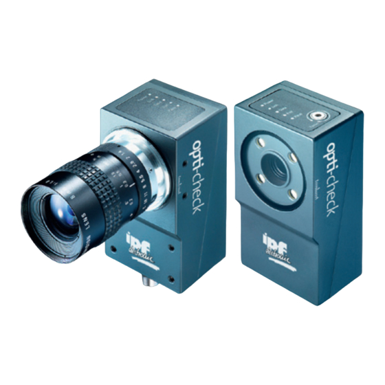
opti-check
Important safety instructions
WARNING!
ATTENTION!
opti-check emits bright, pulsed light
(Risk goup 1).
Bright, pulsed light can cause damage
to the eyes and seizures.
Never look directly into the pulsed
light from the LEDs!
Detailed safety instructions can be found in technical documentation, chapter 3.
Conformity:
Operating conditions
Storage temp.
-20 °C ... +70 °C
Operating temp.
+5 °C ... +50 °C
Housing temp.
max. +50 °C
Humidity
0 % ... +90 %
(non-condensing)
© ipf electronic gmbh, Rosmarter Allee 14, DE-58762 Altena,
Germany.
http://www.ipf.de · hotline@ipf.de
Revisions in the course of technical progress and any errors reserved.
Reproduction of this document in whole or in part is only permitted
with previous written consent from ipf electronic gmbh.
Printed in Germany. 01/14 (valid from v2.4-K11)
Mechanical setup
NOTE
Separate mounting brackets are
available as accessories. For
reflective objects, the opti-check
can be tilted approx. 5° to 15° to
avoid reflections.
The field of view and the minimum
module size for the OC5396XX /
OC5397XX depend on the lens
installed.
160
Width
Height
120
80
f = 10 mm*
40
0
50
100
Fields of view
(OC5391XX / OC5392XX / OC5393XX / OC5394XX / OC5395XX)
* Working distances > 400 mm possible
Getting started
For optimum electrical noise
immunity, the use of shielded
cables is recommended.
The appropriate cables can be
obtained from ipf electronic gmbh.
Ethernet connection
Working distance opti-check
1.0
Matrix code
0.8
Barcode
0.6
f = 10 mm*
0.4
External
0.2
f = 16 mm
illumination
recommended
200
300
400
0
50
100
200
Working distance [mm]
Working distance [mm]
Minimum modul sizes
(OC5392XX / OC5393XX / OC5394XX / OC5395XX)
Place the enclosed CD in the CD drive and follow the instructions
on the screen. After successful installation, links to the
Application Suite are placed on the desktop.
You can now start the program. Connect the opti-check to the
Ethernet interface of your computer and log on both the opti-
check and your PC within the same network.
By default, the use of DHCP is enabled. If a DHCP server is not
found within 15 seconds, the following network configuration is
used:
192.168.0.250
IP address:
Subnet mask: 255.255.255.0
NOTE
To avoid network malfunctions, ensure that each IP address is
unique within your network!
Installation and timing
ATTENTION!
Incorrect voltage will destroy the device: Pin 1: Power (+18...30 VDC)
Electrical connection*
M12 / 12-pin
7
6
8
9
5
12
11
1
4
10
2
3
1: PWR (+18...30 VDC) Brown
7: OUT3
2: Ground
Blue
8: IN3
3: IN1 (Trigger)
White
9: OUT4 / RS485+
4: OUT1
Green
10: IN4
5: IN2
Pink
11: IN5
6: OUT2
Yellow
12: OUT5 / RS485-
* on device
f = 16 mm
300
400
The duration of the output signals and the time of output are adjusted by software and
depend on the current job.
Application Suite
The Application Suite helps you to create, manage and test jobs and to configure them
for Real-time mode.
Image display
options
Display screen
Job bar
Device menu
Job menu
Commissioning is usually conducted in Live image mode or
Images from PC on the basis of sample images. You can select the
mode with the buttons alternatively.
LOAD IMAGE
SAVE CURRENT IMAGE
START LIVE IMAGE RECORDING
NAVIGATING IN LOADED IMAGES
Jobs are created in three main steps, using the Job bar.
Pin 2: Ground
Ethernet*
Electr. connection illumination*
M12 / 4-pin
M8 / 4-pin (XC only)**
3
4
1
3
2
1
2
4
Black
1: TD+
1: +24 V bzw. +48 V Flash
Gray
2: RD+
2: +12 V bzw. +24 V Flash
Red
3: TD-
3: Ground
Violet
4: RD-
4: Flash Sync
Gray-Pink
Red-Blue
** Voltage outputs configurable by software
Help, info und support
window
Parameter area
Advertisement

Related Manuals for ipf electronic OC539E21


Summary of Contents for ipf electronic OC539E21
- Page 1 (non-condensing) LOAD IMAGE SAVE CURRENT IMAGE 192.168.0.250 IP address: © ipf electronic gmbh, Rosmarter Allee 14, DE-58762 Altena, Subnet mask: 255.255.255.0 START LIVE IMAGE RECORDING Germany. http://www.ipf.de · hotline@ipf.de NAVIGATING IN LOADED IMAGES Revisions in the course of technical progress and any errors reserved.
- Page 2 Creating a job in 4 steps Overview feature checks Launch of opti-check Application Suite Add new feature checks Part location Choose your device in the selection list. With Example: CONNECT button, you connect with the selected opti-check vision Setting of feature check BRIGhTNESS Part location Part location...
Need help?
Do you have a question about the OC539E21 and is the answer not in the manual?
Questions and answers