
Related Manuals for EDA CM4 INDUSTRIAL


Summary of Contents for EDA CM4 INDUSTRIAL
- Page 1 User Manual of CM4 Industrial V1.4 CM4 INDUSTRIAL AN INDUSTRIAL EMBEDDED COMPUTER BASED ON RASPBERRY PI CM4 Shanghai EDA Technology Co.,Ltd 2023-03-22 EDA Technology Co.,LTD– Electronics Development Accelerator...
- Page 2 Disclaimers Shanghai EDA Technology Co., Ltd does not guarantee that the information in this manual is up to date, correct, complete or of high quality. Shanghai EDA Technology Co., Ltd also does not guarantee the further use of this information.
-
Page 3: Table Of Contents
User Manual of CM4 Industrial V1.4 Contents Product Overview ..........................5 Target Application ........................5 Specifications and Parameters ....................5 System Diagram ......................... 7 Functional Layout ........................7 Packing List ..........................9 Order Code ..........................9 Quick Start ............................10 Equipment List ......................... - Page 4 User Manual of CM4 Industrial V1.4 4.4.2 Example ........................30 4G LTE ............................. 31 RTC ............................32 Button ............................34 4.7.1 Reset Button........................34 4.7.2 User Button ........................34 LED Indication .......................... 34 Buzzer ............................34 4.10 SPI Flash ..........................35 4.11...
-
Page 5: Product Overview
PoE function, one 10/100M network port, 4G/LTE module, certified 2.4/5.8G dual-band WiFi and Bluetooth, and supports external antennas. CM4 Industrial can support 2 CSI interfaces, 1 DSI display interface and 1 HDMI cable interface. Other features include on-board 32Mb serial Flash for storing system data, wide power supply range, V1.4 version is 9~36V, V1.1~V1.3 version is 9~18V, and ESD protection for important interfaces. - Page 6 User Manual of CM4 Industrial V1.4 Function Parameters Camera 2x CSI, Support official 5M/8M/12M cameras 2x USB 2.0 Type A, 1x USB 2.0 integrated in Mini PCIe interface, 2x USB USB Host 2.0 Host Pin Header extend, 1x USB micro-B used for eMMC flash...
-
Page 7: System Diagram
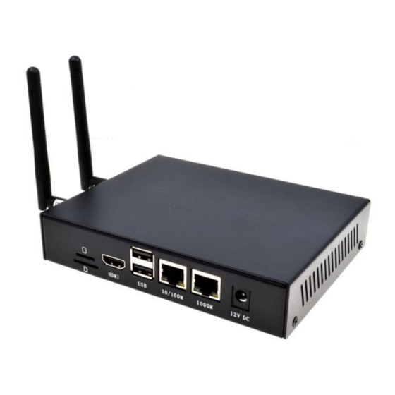
User Manual of CM4 Industrial V1.4 1.3 System Diagram Note: V1.4 version power input range is 9V~36V, V1.1~V1.3 version power input range is 9V~18V. 1.4 Functional Layout EDA Technology Co.,LTD– Electronics Development Accelerator... - Page 8 User Manual of CM4 Industrial V1.4 Function Function 2×ADC Debug serial port RS232 Customize GPIO Pin Header 2×RS485 DC power socket 2×DIN Gigabit Ethernet RJ45 port 2×relay 100 Gigabit Ethernet RJ45 port Reset button 2×USB 2.0 Signal indicating LED HDMI Type A...
-
Page 9: Packing List
User Manual of CM4 Industrial V1.4 Function Function mini PCIe interface CM4 socket Standard SIM slot 1.5 Packing List 1x CM4 Industrial host computer [option WiFi/BT version] 1x 2.4GHz/5GHz WiFi/BT antenna [option 4G version] 1x 4G/LTE antenna 1.6 Order Code... -
Page 10: Quick Start
1x CR1220 button battery (RTC power supply) 2.2 Hardware Connection Use the device with case, eMMC, WiFi and 4G module as an example to demonstrate how to install it. In addition to the CM4 Industrial host computer, you also need: 1x Network cable... -
Page 11: First Start
4.Mouse and keyboard plugged into USB interface. 5.Plug in the HDMI cable and connect the monitor. 6.Power the 12V@2A power adapter and plug it into the DC power input port of CM4 Industrial (marked with +12V DC). 2.3 First Start CM4 Industrial has no power switch. - Page 12 User Manual of CM4 Industrial V1.4 If you use the official system image, and the image is not configured before burning, the Welcome to Raspberry Pi application will pop up and guide you to complete the initialization setting when you start it for the first time.
- Page 13 User Manual of CM4 Industrial V1.4 Select the wireless network you need to connect to, enter the password, and then click Next. NOTE: If your CM4 module does not have a WIFI module, there will be no such step.
-
Page 14: Raspberry Pi Os (Lite)
User Manual of CM4 Industrial V1.4 Click Restart to complete the system update. 2.3.2 Raspberry Pi OS (Lite) If you use the system image provided by us, after the system starts, you will automatically log in with the user name pi, and the default password is raspberry. -
Page 15: Use Ssh
User Manual of CM4 Industrial V1.4 Creat new user name Then set the password corresponding to the user according to the prompt, and enter the password again for confirmation. At this point, you can log in with the user name and password you just set. -
Page 16: Get The Device Ip
User Manual of CM4 Industrial V1.4 2.3.3.2 Add Empty File To Enable SSH Put an empty file named ssh in the boot partition, and the SSH function will be automatically enabled after the device is powered on. 2.3.4 Get The Device IP ... - Page 17 User Manual of CM4 Industrial V1.4 3.1.2 DI CM4 Industrial has two channels of digital input detection with isolation. There are only two states of digital input: high level and low level. There are two connection methods for digital input signals, namely dry contact (passive) connection and wet contact (active) connection.
- Page 18 User Manual of CM4 Industrial V1.4 In the field of industrial control, three wire PNP type and NPN type sensors are the most common. Among the three wires, usually brown represents the positive electrode (VCC), blue represents the negative electrode (GND), and black represents the signal output terminal (OUT).
- Page 19 User Manual of CM4 Industrial V1.4 WARN: Vout can only provide 12V power output. NPN type sensors are also known as sinking input mode sensors. When a signal is triggered, the OUT signal terminal outputs a low level. The connection diagram of NPN type sensor is as follows.
-
Page 20: Relay
Relay output interfaces NC, COM and NO correspond to normally closed, common interface and normally open relay respectively. The relay on board CM4 Industrial is a double-pole, double-throw relay. When the control relay is closed, NO1 and NO2 are closed relative to COM1 and COM2, and when the control relay is bounced off, NO1 and NO2 are open relative to COM1 and COM2. -
Page 21: Rs485
Taking RS485-1 interface as an example, the wiring diagram is as follows: 3.1.6 micro-SD Card There is a micro SD card slot on CM4 Industrial. Please insert the micro SD card face up into the micro SD card slot. 3.1.7 SIM Card... -
Page 22: Internal I/O
User Manual of CM4 Industrial V1.4 CM4 Industrial uses standard SIM card, please insert the chip end of the SIM card into the SIM card slot. 3.2 Internal I/O 3.2.1 DSI The DSI interface should be connected with a single-sided FPC cable with a spacing of 15pin 1mm, with the metal contact face up and inserted in the direction perpendicular to the FPC connector, as shown in the following figure. -
Page 23: Software Operation Guide
User Manual of CM4 Industrial V1.4 4 Software Operation Guide 4.1 USB 2.0 4.1.1 Check USB Device Information List USB device lsusb The information displayed is as follows: Bus 002 Device 001: ID 1d6b:0003 Linux Foundation 3.0 root hub Bus 001 Device 005: ID 1a2c:2d23 China Resource Semico Co., Ltd Keyboard Bus 001 Device 004: ID 30fa:0300 USB OPTICAL MOUSE Bus 001 Device 003: ID 0424:9e00 Microchip Technology, Inc. - Page 24 User Manual of CM4 Industrial V1.4 After using, use the command umount to uninstall the storage device. sudo umount /mnt 4.1.2.1 Mount You can install the storage device in a specific folder location. It is usually done in the /mnt folder, such as /mnt/mydisk.
-
Page 25: Ethernet Configuration
4.2 Ethernet Configuration 4.2.1 Gigabit Ethernet There is an adaptive 10/100/1000Mbsp Ethernet interface on CM4 Industrial, which is adjacent to the DC power socket. It is recommended to use Cat6 (Category 6) network cable to cooperate with it. By default, the system uses DHCP to automatically obtain IP. -
Page 26: Using The Network Manager To Configure
User Manual of CM4 Industrial V1.4 Usage: { prog addr | read | erase } read MAC address sudo ./lan9500-mac-addr-set.sh read erase sudo ./lan9500-mac-addr-set.sh read burn MAC address and restart takes effect sudo ./lan9500-mac-addr-set.sh prog aa:bb:cc:dd:ee:ff Program MAC address: aa:bb:cc:dd:ee:ff..OK sudo reboot 4.2.3 Using The Network Manager To Configure... - Page 27 User Manual of CM4 Industrial V1.4 Switch to the configuration page of IPv4 Settings. If you want to set static IP, the Method selects Manual, and Addresses the IP you want to configure. If you want to set it as dynamic IP acquisition, just configure the Method as Automatic(DHCP) and restart the device.
-
Page 28: Configuration With Dhcpcd Tool
8.8.8.8 fd51:42f8:caae:d92e::1 4.3 WiFi Customers can purchase CM4 Industrial with WiFi version, which supports 2.4 GHz and 5.0 GHz IEEE 802.11 b/g/n/ac dual-band WiFi. We provide dual-band external antenna, which has passed wireless authentication together with Raspberry Pi CM4. -
Page 29: External Antenna And Internal Pcb Antenna
User Manual of CM4 Industrial V1.4 4.3.1.1 Configure Using The Network Manager Tool. After installing the desktop plug-in, you can directly connect to the WIFI network through the desktop icon. You can also use the command line to execute the following commands:... -
Page 30: Ap And Bridge Mode
4.4 Bluetooth CM4 Industrial can choose whether the Bluetooth function is integrated. If it is, this function is turned on by default. Bluetoothctl can be used to scan, pair and connect Bluetooth devices. Please refer to the... -
Page 31: Lte
Changing 34:12:F9:91:FF:68 trust succeeded 4.5 4G LTE CM4 Industrial supports 4G networks. If you choose products with 4G modules, we have configured the mobile EC20 full netcom 4G module in China, which supports mobile, Unicom and telecom network standards. The 4G module is extended by USB 2.0, and supports one Standard-SIM card. -
Page 32: Rtc
4.6 RTC CM4 Industrial is integrated with RTC. For the version sold in China, we will install CR1220 button cell (RTC backup power supply) by default when shipping. In this way, the system can be guaranteed to have an uninterrupted and reliable clock, which is not affected by factors such as equipment power EDA Technology Co.,LTD–... - Page 33 When the system is shut down, the service automatically writes the system time into RTC and updates the RTC time. Because of the installation of button cell, although CM4 Industrial is powered off, RTC is still working and timing. In this way, we can ensure that our time is accurate and reliable.
-
Page 34: Button
A level of 0 indicates that the GPIO6 pin is low. 4.8 LED Indication CM4 Industrial has two indicator lights, the red LED is connected with the LED_PI_nPWR pin of CM4, which is the power indicator light, and the green LED is connected with the LED_PI_nACTIVITY pin of CM4, which is the running status indicator light. -
Page 35: Spi Flash
Op means set to output, and dl means pin is low. 4.10 SPI Flash CM4 Industrial has extended a piece of SPI Flash, 32Mbits, that is, 4MByte, for guests to store data, etc. On Linux, serial Flash is recognized as MTD(Memory Technology Device) device, and on CM4 Industrial, the device file of this Flash is /dev/mtd0. -
Page 36: Install Picocom Tool
Type Ctrl+a first, then Ctrl+q to exit picocom. 4.11.2 RS232 Connect the RS232 serial port of CM4 Industrial with the RS232 serial port of external equipment. The RS232 serial port of CM4 Industrial corresponds to the device file /dev/ttyAMA3. Execute the following instructions to open the serial port and configure the baud rate to 115200. -
Page 37: Rs485
/boot/cmdline.txt 4.12 ADC ADC driver is supported by using CM4 Industrial factory image. If you use the official image of Raspberry Pi, please refer to Install BSP Online Based On The Original Raspberry Pi There are 3 ADC channels on CM4 Industrial. -
Page 38: Relay
GPIO 26: level=0 fsel=0 func=INPUT pull=DOWN 4.14 Relay CM4 Industrial has a double-pole double-throw relay on board, and its switch is controlled by the high and low level of GPIO22 pin. By default, it is normally closed, COM1 and NC1 are on, and COM2 and NC2 are on. -
Page 39: Operating System Installation
C:\Program Files (x86)\Raspberry Pi\rpiboot.exe。 When the CM4 Industrial is powered on, the CM4 eMMC will be recognized as a mass storage device. Use the image burning tool to burn your image to the identified mass storage device. EDA Technology Co.,LTD– Electronics Development Accelerator... -
Page 40: Install Bsp Online Based On The Original Raspberry Pi Os
-sS https://apt.edatec.cn/pubkey.gpg | sudo apt-key add - echo "deb https://apt.edatec.cn/raspbian stable main" | sudo tee /etc/apt/sources.list.d/edatec.list 2. Then, install the BSP package CM4 Industrial hardware version V1.1 or V1.2 execution. sudo apt update sudo apt install raspberrypi-kernel raspberrypi-kernel-headers sudo apt install ed-cm4ind-rev1p1-bsp ed-rtc CM4 Industrial hardware version V1.3 or V1.4 execution. -
Page 41: About Us
User Manual of CM4 Industrial V1.4 7 About us 7.1 About EDATEC EDATEC, located in Shanghai, is one of Raspberry Pi's global design partners. Our vision is to provide hardware solutions for Internet of Things, industrial control, automation, green energy and artificial intelligence based on Raspberry Pi technology platform.
Need help?
Do you have a question about the CM4 INDUSTRIAL and is the answer not in the manual?
Questions and answers