Table of Contents
Advertisement
INSTALLATION INSTRUCTIONS
R−410A Split System Heat Pumps
These instructions must be read and understood completely before attempting installation.
NOTE: Read the entire instruction manual before starting the
installation.
SAFETY CONSIDERATIONS
Improper installation, adjustment, alteration, service, maintenance,
or use can cause explosion, fire, electrical shock, or other
conditions which may cause death, personal injury, or property
damage. Consult a qualified installer, service agency, or your
distributor or branch for information or assistance. The qualified
installer or agency must use factory–authorized kits or accessories
when modifying this product. Refer to the individual instructions
packaged with the kits or accessories when installing.
Follow all safety codes. Wear safety glasses, protective clothing,
and work gloves. Use quenching cloth for brazing operations.
Have fire extinguisher available. Read these instructions
thoroughly and follow all warnings or cautions included in
literature and attached to the unit. Consult local building codes and
current editions of the National Electrical Code (NEC) NFPA 70.
In Canada, refer to current editions of the Canadian electrical code
CSA 22.1.
Recognize safety information. This is the safety–alert symbol
When you see this symbol on the unit and in instructions or
manuals, be alert to the potential for personal injury.
Understand these signal words; DANGER, WARNING, and
CAUTION. These words are used with the safety–alert symbol.
DANGER identifies the most serious hazards which will result in
severe personal injury or death.
which could result in personal injury or death. CAUTION is used
to identify unsafe practices which may result in minor personal
injury or product and property damage. NOTE is used to highlight
suggestions which will result in enhanced installation, reliability, or
operation.
WARNING
!
ELECTRICAL SHOCK HAZARD
Failure to follow this warning could result in personal injury
or death.
Before installing, modifying, or servicing system, main
electrical disconnect switch must be in the OFF position.
There may be more than 1 disconnect switch. Lock out and
tag switch with a suitable warning label.
WARNING
!
EXPLOSION HAZARD
Failure to follow this warning could
result in death, serious personal injury,
and/or property damage.
Never use air or gases containing
oxygen for leak testing or operating
refrigerant compressors.
mixtures of air or gases containing
oxygen can lead to an explosion.
N4H4−G / R4H4−B / WCH4−B
! !
.
WARNING signifies hazards
Pressurized
INSTALLATION RECOMMENDATIONS
NOTE: In some cases noise in the living area has been traced to
gas pulsations from improper installation of equipment.
1. Locate unit away from windows, patios, decks, etc. where
unit operation sound may disturb customer.
2. Ensure that vapor and liquid tube diameters are appropriate
for unit capacity.
3. Run refrigerant tubes as directly as possible by avoiding un-
necessary turns and bends.
4. Leave some slack between structure and unit to absorb vi-
bration.
5. When passing refrigerant tubes through the wall, seal open-
ing with RTV or other pliable silicon–based caulk (see Fig.
1).
6. Avoid direct tubing contact with water pipes, duct work,
floor joists, wall studs, floors, and walls.
7. Do not suspend refrigerant tubing from joists and studs with
a rigid wire or strap which comes in direct contact with
tubing (see Fig. 1).
8. Ensure that tubing insulation is pliable and completely sur-
rounds vapor tube.
9. When necessary, use hanger straps which are 1 in. wide and
conform to shape of tubing insulation (see Fig. 1).
10. Isolate hanger straps from insulation by using metal sleeves
bent to conform to shape of insulation.
OUTDOOR WALL
CAULK
INSULATION
THROUGH THE WALL
HANGER STRAP
(AROUND SUCTION
TUBE ONLY)
1" (25.4 mm)
MIN
SUSPENSION
Fig. 1 – Connecting Tubing Installation
When outdoor unit is connected to factory–approved indoor unit,
outdoor unit contains system refrigerant charge for operation with
AHRI rated indoor unit when connected by 15 ft. (4.57 m) of
field–supplied or factory accessory tubing. For proper unit
operation, check refrigerant charge using charging information
located on control box cover and/or in the Check Charge section of
this instruction.
IMPORTANT: Maximum liquid–line size is 3/8–in. OD for all
residential applications including long line.
IMPORTANT: Always install the factory–supplied liquid–line
filter drier. Obtain replacement filter driers from your distributor or
branch.
INDOOR WALL
LIQUID TUBE
SUCTION TUBE
JOIST
INSULATION
SUCTION TUBE
LIQUID TUBE
A07588
428 01 5107 01
03/04/15
Advertisement
Table of Contents

Related Manuals for Grandaire N4H4-G


Summary of Contents for Grandaire N4H4-G
- Page 1 INSTALLATION INSTRUCTIONS R−410A Split System Heat Pumps N4H4−G / R4H4−B / WCH4−B These instructions must be read and understood completely before attempting installation. NOTE: Read the entire instruction manual before starting the INSTALLATION RECOMMENDATIONS installation. NOTE: In some cases noise in the living area has been traced to SAFETY CONSIDERATIONS gas pulsations from improper installation of equipment.
-
Page 2: Installation
On rooftop applications, locate unit at least 6 in. above roof INSTALLATION surface. IMPORTANT: Effective January 1, 2015, all split system and packaged air conditioners must be installed pursuant to applicable 3/8–in. (9.53 mm) Dia. regional efficiency standards issued by the Department of Energy. Tiedown Knockouts in Basepan(2) Places CAUTION... -
Page 3: Make Piping Connections
Table 1 – Accessory Usage REQUIRED FOR LOW–AMBIENT REQUIRED FOR REQUIRED FOR Accessory COOLING APPLICATIONS SEA COAST APPLICATIONS LONG LINE APPLICATIONS* (Below 555F / 12.85C) (Within 2 miles / 3.22 km) Accumulator Standard Standard Standard Compressor Start Assist Capacitor and Relay Crankcase Heater Evaporator Freeze Thermostat... -
Page 4: Fire Hazard
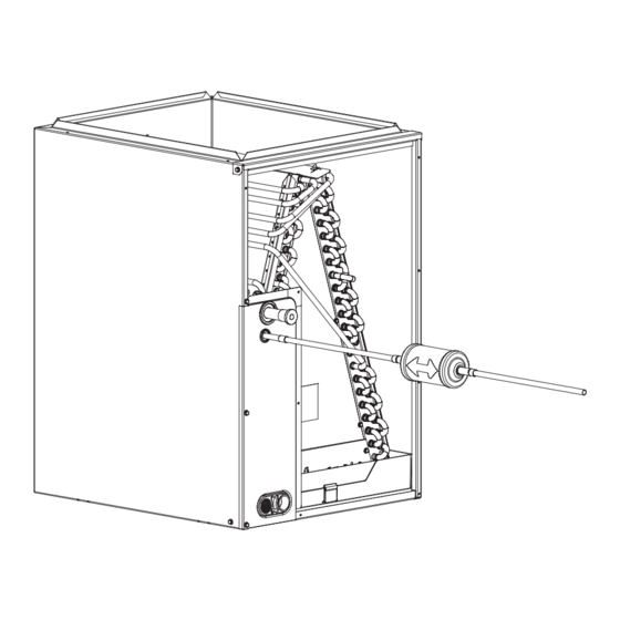
Table 2 – Refrigerant Connections and Recommended Liquid and Vapor Tube Diameters (In.) LIQUID RATED VAPOR UNIT SIZE SERVICE VALVE Connection Tube Connection Tube Diameter Diameter Diameter Diameter VALVE CORE 18, 24 30, 36 42, 48 1–1/8 * Units are rated with 25 ft. (7.6 m) of lineset. See Product Data sheet for performance data when using different size and length linesets. -
Page 5: Make Electrical Connections
Make Electrical Connections CAUTION WARNING UNIT DAMAGE HAZARD Failure to follow this caution may result in equipment damage ELECTRICAL SHOCK HAZARD or improper operation. Failure to follow this warning could result in personal injury or Installation of filter drier in liquid line is required. death. - Page 6 Table 3 – 3–Phase Monitor LED Indicators Install Electrical Accessories STATUS Refer to the individual instructions packaged with kits or No call for compressor operation accessories when installing. FLASHING Reversed phase Normal Start–Up Connect Control Wiring CAUTION Route 24v control wires through control wiring grommet and connect leads to control wiring.
-
Page 7: Check Charge
NOTE: If indoor unit is equipped with a time–delay relay circuit, To initiate defrost, the defrost thermostat must be closed. This can be accomplished as follows: the indoor blower will run an additional 90 seconds to increase system efficiency. 1. Turn off power to outdoor unit. Heating 2. - Page 8 when the outdoor temperature is between 70_F and 100_F If the indoor temperature is below 70_F (21.11_C), or the outdoor (21.11_C and 37.78_C), and the indoor temperature is between temperature is not in the favorable range, adjust charge for line set 70_F and 80_F (21.11_C and 26.67_C).
- Page 9 Units with Indoor Pistons 7. Refer to Table 9. Find superheat temperature located in item 6 and suction pressure. At this intersection, note suction line Units installed with indoor pistons require charging by the temperature. superheat method. 8. If unit has a higher suction line temperature than charted The following procedure is valid when indoor airflow is within temperature, add refrigerant until charted temperature is "21 percent of its rated CFM.
- Page 10 Table 6 – Additional Subcooling Required − WCH4−B Subcooling Delta from Rating Plate Value Outdoor Unit Tonnage Indoor Unit | Additional Subcooling Required WLA*184AA* WLA*244AA* WLA*304AA* WLA*364AA* WLA*424CA* WLA*484BA* WLA*604CA* WLA*244AA* WLA*244BA* WLA*304BA* WLA*364BA* WLA*424DA* WLA*484CA* WLA*604DA* WLA*244BA* WLA*254BA* WLA*364AA* WLA*364CA* WLA*434CA* WLA*484DA*...
- Page 11 Table 7 – Required Liquid Line Temperatures _F LIQUID PRESSURE AT REQUIRED SUBCOOLING TEMPERATURE (°F) SERVICE VALVE (PSIG) Table 8 – Superheat Charging (Heat Pump Only) EVAPORATOR ENTERING AIR TEMPERATURE (°F WB) OUTDOOR TEMP (°F) – – – – – –...
-
Page 12: Final Checks
FINAL CHECKS CARE AND MAINTENANCE IMPORTANT: Before leaving job, be sure to do the following: For continuing high performance and to minimize possible equipment failure, periodic maintenance must be performed on this 1. Ensure that all wiring is routed away from tubing and sheet equipment.
Need help?
Do you have a question about the N4H4-G and is the answer not in the manual?
Questions and answers