Table of Contents
Advertisement
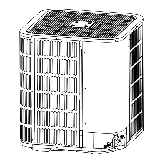
NOTE: Appearance of unit may vary.
ALL phases of this installation must comply with NATIONAL, STATE AND LOCAL CODES
IMPORTANT - This Document is customer property and is to remain with this unit. Please return to service information
pack upon completion of work.
These instructions do not cover all variations in systems or provide for every possible contingency to be met in connection with the in-
stallation. Should further information be desired or should particular problems arise which are not covered sufficiently for the purchaser's
purposes, the matter should be referred to your installing dealer or local distributor.
Note : The manufacturer recommends installing only approved matched indoor and outdoor systems. All of the manufac-
turer's split systems are A.H.R.I. rated only with TXV indoor systems. Some of the benefits of installing approved matched
indoor and outdoor split systems are maximum efficiency, optimum performance and the best overall system reliability.
Table of Contents
Section 1. Safety............................................................................2
Section 2. Unit Location Considerations.....................................3
Section 3. Unit Preparation...........................................................5
Section 4. Setting the Unit............................................................5
Section 5. Refrigerant Line Considerations................................6
Section 6. Refrigerant Line Routing.............................................7
Section 7. Refrigerant Line Brazing.............................................8
Section 8. Refrigerant Line Leak Check....................................10
Section 9. Evacuation..................................................................11
Section 10. Service Valves..........................................................11
Section 11. Electrical - Low Voltage...........................................12
Section 12. Electrical - High Voltage..........................................13
Section 13. Start Up.....................................................................14
Section 14. System Charge Adjustment....................................15
Section 15. System operation and Troubleshooting.................19
Installer's Guide
Condensing Units
1
Split System Heat Pump
Up to 18 SEER
2-3-4-5 Ton Capacity
R410A
Advertisement
Table of Contents

Related Manuals for Grandaire 4860


Summary of Contents for Grandaire 4860
-
Page 1: Table Of Contents
Installer’s Guide Condensing Units Split System Heat Pump Up to 18 SEER 2-3-4-5 Ton Capacity R410A NOTE: Appearance of unit may vary. ALL phases of this installation must comply with NATIONAL, STATE AND LOCAL CODES IMPORTANT — This Document is customer property and is to remain with this unit. Please return to service information pack upon completion of work. -
Page 2: Section 1. Safety
Section 1. Safety CAUTION Important - This document contains a wiring diagram and service information. This is customer property and is CONTAINS REFRIGERANT! to remain with this unit. Please return to service informa- Failure to follow proper procedures can result in tion pack upon completion of work. -
Page 3: Section 2. Unit Location Considerations
Models H x W x L(Inches) 2436 24-15/16 x 29-1/8 x 29-1/8 4860 33-3/16 x 29-1/8 x 29-1/8 See Product Specifications for unit's weight. When mounting the outdoor unit on a roof, be sure the roof will support the unit’s weight. - Page 4 2.4 Location Restrictions Av oid Install Ensure the top discharge area is unrestricted for Near Bedroom s at least 60 inches above the unit. Min. 60” Unrestricted Do not locate outdoor unit near bedrooms since normal Min. 24” Min. 20” to Unrestricted operational sounds may be objectionable.
-
Page 5: Section 3. Unit Preparation
Section 3. Unit Preparation 3.1 Prepare The Unit For Installation STEP 1 - Check for damage and report promptly to the carrier any damage found to the unit. The charge port can be used to check to be sure the refrigerant charge has been retained during shipment. -
Page 6: Section 5. Refrigerant Line Considerations
Liquid Line Model Line Line Connection Connection 2436 4860 5.2 Required Refrigerant Line Length Determine required line length. Line Lengt h 5.3 Refrigerant Line Insulation Important: The Suction Line must always be insulated. DO NOT allow the Liquid Line and... -
Page 7: Section 6. Refrigerant Line Routing
5.4 Reuse Existing Refrigerant Lines CAUTION If using existing refrigerant lines make certain that all joints are brazed, not soldered. For retrofit applications, where the existing refrigerant lines will be used, the following precautions should be taken: • Ensure that the refrigerant lines are the correct size. -
Page 8: Section 7. Refrigerant Line Brazing
8 Feet Maximum Wall Isolator Line Set 8 Feet Maximum Side View Secure Suction Line using isolators every 8 ft. Secure Liquid Line directly to Suction Line using tape, wire, or other appropriate method every 8 ft. Isolation In Wall Spaces Wall Sealant Ductwork... - Page 9 STEP 2 - Remove the pressure port cap from both service valves. STEP 3 - Purge the refrigerant lines and indoor coil with dry nitrogen. This pipe must have a thimble STEP 4 - Wrap a wet rag around the valve body to avoid heat damage and continue the dry nitrogen purge.
-
Page 10: Section 8. Refrigerant Line Leak Check
STEP 5 - Replace the pressure tap caps after the service valves have cooled. Section 8. Refrigerant Line Leak Check 8.1 Check For Leaks STEP 1 - Pressurize the refrigerant lines and evapo - 150 PSI G rator coil to 150 PSIG using dry nitrogen. STEP 2 - Check for leaks by using a soapy solution or bubbles at each brazed location. -
Page 11: Section 9. Evacuation
REQUIRED PARTS LIST Section 9. Evacuation 9.1 Evacuate the Refrigerant Lines and Indoor Coil Important: Do not open the service valves until the refrigerant lines and indoor coil leak check and evacuation are complete. 0350 Micr ons STEP 1 - Evacuate until the micron gauge reads no higher than 350 microns, then close the valve to the vacuum pump. -
Page 12: Section 11. Electrical - Low Voltage
Section 11. Electrical - Low Voltage 11.1 Low Voltage Maximum Wire Length Table 11.1 defines the maximum total length of low Table 11.1 voltage wiring from the outdoor unit, to the indoor 24 VOLTS unit, and to the thermostat. WIRE SIZE MAX. -
Page 13: Section 12. Electrical - High Voltage
Section 12. Electrical - High Voltage 12.1 High Voltage Power Supply WARNING LIVE ELECTRICAL COMPONENTS! During installation, testing, servicing, and trouble - shooting of this product, it may be necessary to work with live electrical components. Failure to fol - low all electrical safety precautions when exposed to live electrical components could result in death or serious injury. -
Page 14: Section 13. Start Up
Section 13. Start Up 13.1 System Start Up STEP 1 - Ensure Sections 7, 8, 9, 10, 11, 12, and 13 have been completed. STEP 2 - Set System Thermostat to OFF. OF F D O N E CANCEL STEP 3 - Turn on disconnect to apply power to the indoor and outdoor units. -
Page 15: Section 14. System Charge Adjustment
Section 14. System Charge Adjustment 14.1 charging: weigh-In Method weigh-In Method can be used for the Initial installation, or anytime a system charge is being replaced. weigh-In Method can also be used when power is not available to the equipment site or operating conditions (indoor/Outdoor tempera- tures) are not In range to verify with the subcooling charging method. - Page 16 14.2 Subcooling charging and refrigerant adjustment in cooling (above 55 F outdoor temp.) STEP 1 - Check the outdoor ambient temperatures. 120 ºF Outdoor Subcooling (in cooling charge mode) is the only recom- Temperature mended method of charging above 55ºF outdoor ambi- Above 55ºF ent temperatures.
- Page 17 STEP 4 - Calculate superheat value on suction valves(According to form ) R-410A REFRIGERAN CHART Measured Suction Line Temp. = ________ºF FINAL SUPERHEAT(℉) Suction Line Measured Suction Line Pressure = _______ PSIG TEMP (℉) SUCTION GAGE PRESSURE (PSIG) Calculate superheat value = ________ºF Note:Make sure the superheat value of suction valve 105 101 110 105 101...
- Page 18 STEP 6 - Adjust refrigerant level to attain proper gage pressure. Add refrigerant if the design subcooling is lower than the chart value. Connect gages to refrigerant bottle and unit as illustrated. Purge all hoses. Open bottle. Stop adding refrigerant when subcooling. matches the charging chart Final Subcooling value.
-
Page 19: Section 15 System Operation And Troubleshooting
Section 15 System operation and Troubleshooting 1. Control Logic Description ● The variable speed system adopts the same 24VAC control as any conventional Heat Pump. ● The compressor’s speed is controlled based on coil pressures monitored by pressure transducer. To insure stable and adequate capacity, the compressor speed will modulate relative to evaporator pressure during cooling operation and relative to condensing pressure during heating operation. - Page 20 3.Defrost description ● The Demand Defrost Control (DDC) monitors the ODU coil temperature using thermistor (T3). A second thermistor (T4) monitors outdoor ambient temperature. Based on these parameters, as well as accumulative run time and high pressure, the DDC calculates proper initiation of defrost. ●...
- Page 21 4. Compressor Crankcase Heater Description Refrigerant migration during the OFF cycle can result in noisy start-ups, therefore a crankcase heater (CCH) is used to minimize refrigerant migration thereby minimizing start-up noise and/or bearing “wash out”. All CCHs must be installed on the lower half of the compressor shell. Its purpose is to warm the compressor on the OFF cycle, driving refrigerant from compressor.
- Page 22 7. Fault code table CODE FAULT DESCRIPTION Temperature sensor fault (T3 /T4/T5/TF) High/low voltage protection DC fan motor fault System lockup, 2 times(E6),protection in 10 minutes Compressor discharge sensor (T5) is seated fault EEPROM fault Communication fault in main contrrol chip 3 times (P3) protection in 120 minutes,system lockup 3 times (P6) protection in 60 minutes,system lockup 5 times (P2) protection in 100 minutes,system lockup...
- Page 23 8. Parameter Point Check Table ● To display system parameters, press the “Check” button to index through the series of parameters available. ● The LED display has 3 digits. The first digit is the sequence number (0 – 25), however it will only display (0-9) recycling the second digit, for example 24 will display 4.
- Page 24 For 2436 model EEPROM chip THE FACTORY SETTING FOR 36K MODEL, Function description for the corresponding position CUT OFF J2 JUMP FOR 24K MODEL. Content Content Compressor iring terminal Temp. controller connecting port Reactor w iring terminal(connect a reactor betw een 2 and 3 ) Function dial code SW4 Reactor w iring terminal(connect a reactor betw een 2 and 3 ) Spot check button...
- Page 25 For 4860 model Main Control Board THE FACTORY SETTING FOR 60K MODEL, CUT OFF J2 JUMP FOR 48K MODEL. EEPROM chip Drive Board 24 25 26 The photo is just for reference,actual unit will verify.
- Page 26 Function description for the corresponding position (For 48/60k model) N o . C on t ent N o . C on t ent E X V d r i v ing po rt (HP onl y) 19 P oin t c he ck bu tt on H igh p r e ss u r e s w i t c h po rt 20 T e m p .
- Page 27 P8 (Hurricane protection of the DC fan motor (for 4860)) Eb/E6 (DC fan motor fault (for 4860)) Diagnosis Handling Diagnosis Handling Check whether the high speed Reseat the wiring Check whether motor wiring is Insure motor is not influenced operating of fan motor was...
- Page 28 C5/E7 (Compressor discharge sensor(T5) is seated fault) H3/P3 (Compressor over current protection) Diagnosis Handling Diagnosis Handling Fix the discharge temp. Check that sensor is properly Check whether the service sensor to the compressor Open the service valve discharge pipe, re-power seated on discharge pipe.
- Page 29 H8 (Pressure transducer(PT) fault) F1 (High pressure switch(HPS) fault) Diagnosis Handling Diagnosis Handling Wiring according to the Check whether pressure Check whether the service Open the service valve diagram correctly and transducer(PT) wiring is normal valves are open power on to restart Check whether the voltage Check whether high pressure between gauging pressure...
- Page 30 H6/P4 (High discharge temperature(T5) protection of compressor) HH/PH (low discharge superheat protection) Diagnosis Handling Diagnosis Handling Check whether T3/T5/ Check whether the service Pressure Transducer are Open the service valve Replace sensors normal according to Table1, valves are open Table 2 and Table3 Check whether discharge temp.
- Page 31 TABLE 1 (T3 & T4) TEMP F TEMP C RESISTANCE kΩ VOLTS DC TEMP F TEMP C RESISTANCE kΩ VOLTS DC -20.6 107.732 4.65 32.2 7.225 2.36 -17.8 93.535 6.401 2.21 79.521 4.54 37.8 5.683 2.07 -12.2 67.795 4.47 40.6 5.057 1.93 -9.4...
- Page 32 TABLE 3 (Pressure Transducer) NSK-BD035I V= (7.9*PSIG*10 )+0.5 Pe/Pc Pe/Pc Pe/Pc PSIG PSIG PSIG 0.69 24.4 1.37 110.6 2.54 258.5 26.0 1.39 112.5 2.56 262.0 0.72 27.7 114.5 2.59 265.6 0.73 29.4 1.42 116.5 2.62 269.2 0.75 31.2 1.43 118.6 2.65 272.8 0.76...
- Page 34 MD14U-001A 2020XXXXXX...
- Page 35 此页不用印刷! 20150411:更改P18,在过冷度值后增加±2°F 20150419: 按客户要求更改,大改。 20150423:按客户要求在上一次基础上勘误, 跳线说明 20150427:按客户要求更改了Trouble shooting, 大改!...
Need help?
Do you have a question about the 4860 and is the answer not in the manual?
Questions and answers