Advertisement
DYN-6336-01
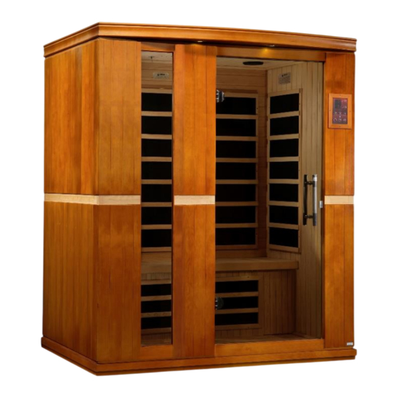
3 Person FAR Infrared Sauna
Owner's Manual
CARBON MODEL SAUNAS
SAUNAS ARE FOR INDOOR USE ONLY
120VAC 20AMP Dedicated Circuit Required
Carefully and thoroughly read this Owner's Manual before using/operating
the sauna. We recommend keeping this Owner's Manual for regular review
and future reference.
1
Advertisement

Related Manuals for Dynamic DYN-6336-01


Summary of Contents for Dynamic DYN-6336-01
- Page 1 DYN-6336-01 3 Person FAR Infrared Sauna Owner’s Manual CARBON MODEL SAUNAS SAUNAS ARE FOR INDOOR USE ONLY 120VAC 20AMP Dedicated Circuit Required Carefully and thoroughly read this Owner’s Manual before using/operating the sauna. We recommend keeping this Owner’s Manual for regular review...
-
Page 2: Table Of Contents
TABLE OF CONTENTS Packing List Visual Assembly Diagram Parts Description Assembly Instructions Operating the Sauna Tips for Using Your Sauna Safety Instructions Safeguards for Your Sauna Troubleshooting Guide Warranty Warranty Card WARNING: Visually inspect all heaters before assembly to make sure they are not damaged. - Page 3 What Are Infrared Rays? Infrared is the band of light we perceive as heat. We cannot see this band of light with the naked eye, but we can feel this type of light in the form of heat. Our sun produces most of its energy output in the infrared segment of the spectrum.
- Page 4 EMF Levels from Common Homes Sources After many years and numerous studies on EMF exposure, no government body including the Occupational Safety and Health Administration (OSHA) have established permissible exposure limits (PEL). Currently, there is no consensus on the potential health hazard from any exposure to EMF.
- Page 5 HOW IT WORKS Infrared Saunas differ from traditional saunas in that they use infrared radiant energy to directly penetrate into the body's tissue to produce perspiration. Traditional saunas use steam to heat the air inside the sauna, which then heats your body until you begin to perspire.
-
Page 6: Visual Assembly Diagram
*PLEASE READ INSTRUCTIONS THOROUGHLY BEFORE ASSEMBLY* Visual Assembly Diagram DYN-6336-01 *THE ABOVE ASSEMBLY DIAGRAM IS FOR A QUICK REFERENCE VISUAL GUIDE ONLY. ALL SAUNA MODELS MAY NOT BE SHOWN. PARTS AND ACCESSORIES DO VARY AND ARE SUBJECT TO CHANGE. -
Page 7: Parts Description
PARTS DESCRIPTION DYN-6336-01 *THE ABOVE ASSEMBLY DIAGRAM IS FOR A QUICK REFERENCE VISUAL GUIDE ONLY. ALL SAUNA MODELS MAY NOT BE SHOWN. PARTS AND ACCESSORIES DO VARY AND ARE SUBJECT TO CHANGE. NOTE: The pictures and diagrams shown above are for representational... - Page 8 Power Supply (Control Box) The POWER SUPPLY is the control center of the sauna room. It is installed on the topside of the ROOF PANEL and has inputs/outputs connected to it. (see Figure 1) Figure 1 POWER IN - main power of the sauna room HT1, HT2, HT3, HT4, HT5, HT6 –...
- Page 9 III. MP3 Auxiliary Port The MP3 Auxiliary Port allows you to connect a MP3 player or other device with the auxiliary function to the speakers in the sauna room for your listening pleasure. (see Figure 2) Figure 2 Buckles External Buckles The external buckles are used to connect the LEFT and RIGHT SIDE PANELS to the REAR PANEL.
- Page 10 Figure 4 Panel Descriptions For easier assembly, please understand and distinguish the differences between each panel. Floor Panel When the FLOOR PANEL faces upward, you will find the floor heat emitter panel on the topside and towards the front of the FLOOR PANEL.
-
Page 11: Assembly Instructions
Rear Panel The REAR PANEL is the panel with the buckles. The buckles are mounted on the exterior side of the REAR PANEL. (see Figure 6) Figure 6 Understanding the Difference Between the Inside and Outside of the Rear Panel You will find the heat emitters on the inside of the REAR PANEL. - Page 12 B. Installing the FLOOR PANEL 1. Place the FLOOR PANEL on the floor. (Note: The floor heater will be located towards the front of the sauna room.) (see Figure 7) Front of Sauna Figure 7 C. Installing the FRONT WALL PANEL, RIGHT SIDE WALL PANEL and LEFT SIDE WALL PANEL 1.
- Page 13 D. Installing the REAR PANEL 1. Remove the protection paper from the buckles on the REAR WALL PANEL. Place the REAR WALL PANEL up onto the FLOOR PANEL. Next, attach the REAR WALL PANEL to the LEFT SIDE WALL PANEL and use the buckles to latch together.
- Page 14 Figure 10 E. Installing the BENCH HEAT EMITTER PANEL and BENCH 1. Installing the BENCH HEAT EMITTER PANEL requires sliding it downward into the guides on the side wall panels. (see Figure 11) 2. Plug in the BENCH HEAT EMITTER connector to the corresponding inlet located on the right side of the REAR WALL PANEL for sauna model DYN-6220-01 and to the corresponding inlet located on the RIGHT SIDE WALL PANEL for sauna models DYN-6306-01/DYN-6330-01/DYN-6440-...
- Page 15 BENCH HEAT EMITTER PANEL Guides On Side Walls Figure 11 (BENCH & BENCH HEAT EMITTER PANEL DO VARY IN INSTALLATION & DESIGN) PLEASE NOTE: If your sauna has the optional LED Accent Lighting above the REAR WALL HEAT EMITTER PANELS and below the BENCH, you will need to connect the connector from the black/white wires coming from the BENCH (located underneath the bench) to the black/white wire connector at the REAR WALL PANEL.
- Page 16 Figure 13 Figure 14 Figure 12 H. Connecting the plugs on the ROOF PANEL (POWER SUPPLY 1) 1. Connect the plugs according to their respective labels. (see Figure 15) 2. You will need to connect the right and left speaker connectors, the MP3 connector, and the CTRL (Panel Control) harness wire connector.
- Page 17 I. Installing the TEMPERATURE SENSOR and Optional SHELF 1. Enter the sauna and remove the protective covering from the TEMPERATURE SENSOR. Situate the TEMPERATURE SENSOR so that it is vertical and pointing downward. (see Figure 17) Figure 17 Note: Some sauna models are shipped with a spare TEMPERATURE SENSOR in case the TEMPERATURE SENSOR is damaged during transit.
- Page 18 Figure 19 Assembly Is Complete!
-
Page 19: Operating The Sauna
Operating the Sauna NOTE: Before the sauna is turned on, remove plastic protective covering from the CONTROL PANELS. Please check and confirm that the connections to the POWER SUPPLY (including the power cord), HEAT EMITTERS, CD/RADIO, and TEMPERATURE SENSOR are connected properly and are snug and tight. The power supply voltage and frequency must match the requested voltage and frequency of the sauna (120VAC 15AMP Dedicated Circuit or 120VAC 20AMP Dedicated Circuit). - Page 20 1. Plug the sauna into the wall outlet. 2. Press the POWER button once. The POWER light will come on, the TIME DISPLAY will show 90 (minutes), the TEMPERATURE DISPLAY will show 151 C, and the control panel will flash. 3.
- Page 21 8. Color Lighting can be operated as follows: First, you will need to install the battery. Once the battery has been inserted into the remote, you are ready to operate the color therapy lighting system . Press the READING LIGHT button on the sauna control panel.
- Page 22 Celsius (depending on sauna model) *45-60 minutes to reach up to approximately 135 degrees Fahrenheit/57 degrees Celsius (depending on sauna model) Please keep in mind that you can either preheat the sauna to the set temperature before entering or sit inside the sauna as the temperature rises. In addition, you will increase the time it takes for the sauna to reach the set temperature if you enter the sauna room before it has reached the set temperature.
-
Page 23: Tips For Using Your Sauna
Tips for using Your Sauna 1. If you take a hot/warm shower or bath before using your sauna, you may perspire more and experience more comfort. 2. Drink water prior to, during, and after your sauna session to replenish body fluids. 3. - Page 24 are closely supervised at all times by an adult. Children should not use the sauna unless prescribed or advised by their medical doctor. 4. Do not use the sauna immediately following strenuous exercises. Wait at least 30 minutes to allow the body to cool down completely. 5.
-
Page 25: Safeguards For Your Sauna
18. Your hands must be dry and free of moisture before plugging and unplugging cords and wiring harnesses from the power supply and circuit boards. Never operate the sauna with wet hands or wet feet to avoid the risk of electrical shock or injury. - Page 26 Troubleshooting Before any troubleshooting of the sauna, make sure to unplug the sauna’s power cord from the wall outlet. If the sauna is hard wired straight to the breaker in the Electric Panel, turn the breaker to the “OFF” position. 1.
- Page 27 roof was installed onto the sauna room. Disconnect the “CTRL” wire harness and firmly reconnect the “CTRL” wire harness making sure it is snug and tight. Attempt to turn the sauna on at the control panel and check to see if the buttons are now responding. Contact the Customer Service for any additional troubleshooting.
- Page 28 towards the rear of the sauna. After you have located the red and black wires labeled “TEMP SENSOR”, disconnect them. Connect the spare temperature sensor. For testing purposes, insert the “TEMP SENSOR” (you just connected) down the vent on the roof so that it is now inside the sauna.
- Page 29 pulling the male connection from the female connection. Reconnect to make sure the connection is snug and tight. Leave the control panel hanging from the wall panel (do not replace with the wood frame as of yet). 4. Next, you can plug the sauna room back into the wall outlet or turn the breaker back “ON”.
- Page 30 musical device and the other end to the MP3 Jack on the ceiling. If the humming sound can no longer be heard, then this confirms that the control panel(s) will need to be replaced. Please contact Customer Service. Solution: If you hear static noises from the speakers when no music is playing, then be sure that the MP3 AUX wire is not plugged into the ceiling port.
- Page 31 know that the heat emitters are working successfully. With even one heat emitter not working correctly, the sauna room will struggle to get above 130 degrees F within the average allotted time. The next test would be to enter the sauna room and to cautiously place your hand on the back side of the bench heat emitter in the center (this would normally be covered by the bench which you already removed).
- Page 32 Extent of Warranty: This limited warranty applies to products manufactured or distributed by Golden Designs, Inc. under the Dynamic brand name, delivered in the continental United States or Canada and extends to the original purchaser at the original site of installation only.
- Page 33 non-approved surfaces Outdoor applications Normal wear and tear or weathering Use of product not in accordance with instructions Worn out receptacle Surface cracks are not considered defects in material or workmanship, as they are normal characteristics of all woods. This includes minor cracks due to wood expansion and contraction.
- Page 34 PAGE INTENTIONALLY LEFT BLANK...
-
Page 35: Warranty Card
WARRANTY CARD Congratulations on your purchase of an Infrared Sauna from Golden Designs, Inc. Please take the time to complete the following Warranty Card and mail it back to: Golden Designs, Inc. 3550 Jurupa Street, Unit B Ontario, CA 91761 Please include a copy of your sales receipt showing date of purchase as this will serve as proof of purchase.
Need help?
Do you have a question about the DYN-6336-01 and is the answer not in the manual?
Questions and answers