TUFFA TANKS ADBLUE 1350SLBFSAD Installation, Operation And Servicing Manual
Adblue
Hide thumbs
Also See for ADBLUE 1350SLBFSAD:
- Installation, operation and servicing manual (40 pages)

Related Manuals for TUFFA TANKS ADBLUE 1350SLBFSAD


Summary of Contents for TUFFA TANKS ADBLUE 1350SLBFSAD
- Page 1 Installation, Operation and Servicing Manual Version 2.0.0 Models: 1350SLBFSAD | 2500HBFSAD | 3500VBFSAD | 6000VBFSAD | 10000VBFSAD | 15000VBFSAD TUFFA ADBLUE® STATIONS...
-
Page 2: Table Of Contents
System installation 6.3 System location 6.4 Electrical requirements 6.5 Electrical wiring diagram Operation of the system 7.1 Using the system 7.2 Summary of main parts 1350 / 2500 Summary of main parts 3500 / 6000 / 10000 / 15000 Filling AdBlue® Station Dispensing AdBlue® into vehicle 7.6 Equipment components Maintenance of the TUFFA TANKS 8.1 System maintenance tasks 8.2 Inspection by competent person 8.3 Internal examination and cleaning 8.4 Troubleshooting 8.5 Tank maintenance record 8.4 AdBlue® delivery log Warranty Contact Guarantee registration... -
Page 3: Introduction
1. INTRODUCTION | 2. CONDITIONS OF USE 3. SAFETY 1. Introduction 3. Safety This manual contains specific instructions and information relating to the installation, PLEASE READ THIS MANUAL CAREFULLY BEFORE USE & COMPLY WITH ALL operation and maintenance of Tuffa Tanks systems. INSTRUCTIONS BELOW. THIS MANUAL SHOULD BE KEPT WITH THE EQUIPMENT AT ALL TIMES. 1. The major hazard involved with installing and operating the unit is electrical shock. This hazard can be avoided if you adhere to the procedures in this manual and exercise 2. -
Page 4: Product Description
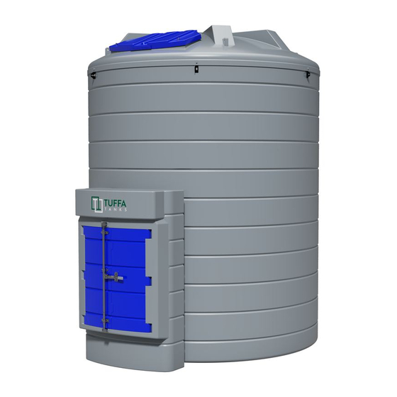
4. PRODUCT DESCRIPTION 4.PRODUCT DESCRIPTION 4.2 Product specification 4. Product description 1350SLBFS 2500HBFS 3500VBFS 6000VBFS 10000VBFS 15000VBFS ® ® ® ® ® ® AdBlue AdBlue AdBlue AdBlue AdBlue AdBlue Capacity 1350 litres 2500 litres 3500 litres 6000 litres 10000 litres 15000 litres Tuffa AdBlue® Stations are designed solely for storage and dispensing of AdBlue®. Length 2680mm 2840mm The static bunded systems enable safe AdBlue® storage and dispensing in an outdoor Width 870mm... -
Page 5: Product Dimensions
4. PRODUCT DESCRIPTION 4.PRODUCT DESCRIPTION Product dimensions 1350SLBFS AdBlue® 3500VBFS AdBlue® 2680 mm 1200 mm 870 mm 2613 mm DESIGNED BY CHECKED BY APPROVED BY DATE MATERIAL DATE Rob Smith J Shenton J Shenton 11/06/2020 10/06/2020 LLDPE 6000VBFS AdBlue® 2500HBFS AdBlue® 3500 BUNDED WITH CABINET DATE MATERIAL... -
Page 6: Transport & Storage
4. PRODUCT DESCRIPTION 5. TRANSPORT & STORAGE 5. Transport & storage 10000VBFS AdBlue® DO NOT TRANSPORT WITH LIQUID INSIDE THE TANK During transportation the flip lid and cabinet doors are secured by 1 x R clip. The R clip must be installed prior to transportation. Loading and off-loading must be carried out by a competent person using suitable rated and maintained equipment, either a forklift with extended forks/tines or a crane. If lifting slings are used, they must be attached to the lifting points as shown in the pictures below using a steel lifting eye insert. If lifting from below use a suitable rated forklift with extended forks. If lifting from above use a suitable rating lifting slings / chains. 1200 mm 3490 mm 1350SLBFSAD / 2500HBFSAD - Lift with main lifting eye highlighted in red in the image below or forklift from the side. DESIGNED BY CHECKED BY APPROVED BY DATE MATERIAL DATE... -
Page 7: Installation & Commissioning
6. INSTALLATION & COMMISSIONING 6. INSTALLATION & COMMISSIONING 6. Installation & commissioning 6.4 Electrical requirements Only a suitably qualified electrician according to applicable regulations may work on the electric wiring installation. The system components under service, maintenance, and repair 6.1 Installation guidelines work must be disconnected from the power supply before any work in undertaken. The proprietor of the Tuffa AdBlue® Station is responsible for complying with all legal require- ments relating to the installation and use of this product, as well as the guidelines issued by System power requirements: local firefighting authorities and environmental authorities. 230V Once the Tuffa AdBlue® Station has been received on site, check that no damage has oc- curred while in transit. Locate the tank in the desired location using either crane, forklift or • 220 - 240 Volts, 50 Hz +/- 10% rollers. • 20 amp circuit breaker recommended • Power cable recommendation: 3 Core 2.5mm flex cable 6.2 System installation • Duty cycle: 20 minutes •... -
Page 8: Operation Of The System
6. INSTALLATION & COMMISSIONING 7. OPERATION OF THE SYSTEM Operation of the system 6.5.2 3500VBFS AdBlue® / 6000VBFS AdBlue® / 10000VBFS AdBlue® / 15000VBFS AdBlue® – Key Switch The system and its components are intended for AdBlue® only and for the purposes de- scribed below. Use of this system in a means other than described below is regarded as mis-use of the system, the user of the system will be liable for any defects that occur due to its unintended use. 7.1 Using the system The operation and maintenance personnel must be suitably trained to use the system, the user must make sure they fully understand the operation and maintenance sections of this manual. 7.2 Summary of main parts 1350 / 2500 (230V) Mains Power Control Panel Clock Gauge Suction Hose... -
Page 9: Summary Of Main Parts 3500 / 6000 / 10000 / 15000
6. INSTALLATION & COMMISSIONING 7. OPERATION OF THE SYSTEM (230V, pulsemeter) (1” top suction) Clock Gauge Mains Power Outlet Control Panel Clock Gauge Suction Hose Dry Break Fill Point Automatic Nozzle Isolation Fill Point Pulsemeter Pulsemeter Valve Remote Display Delivery Hose External Pump 7.3 Summary of main parts 3500 / 6000 / 10000 / 15000 (230V) -
Page 10: Filling Adblue® Station
6. INSTALLATION & COMMISSIONING 7. OPERATION OF THE SYSTEM (Terminating in cabinet) 7.4 Filling AdBlue® Station 1. Filling should be performed only under constant supervision of an authorised person. Isolation Level Gauge & Valve Tank Alarm 2. This tank can only be filled by a tanker equipped with a 2” female dry break coupling. 3. On 3500 / 6000 / 10000 / 15000 models before filling the tank with AdBlue®, please Y-Filter check the level of the tank and make note of the tank level before filling and ensure the high level alarm indicator functions correctly. Mains Junction 4. Fit tanker delivery hose to 2” dry break fill coupling on tank. 5. Engage tanker pump and begin to fill. Stop filling when desired amount has been dispensed into tank, or when high-level alarm sounds. Fill Point 6. During the tanker fill always observe tank level gauge throughout the duration of the filling process. The tanker driver must observe the tank being filled at all times during this process. -
Page 11: Equipment Components
7. OPERATION OF THE SYSTEM 7. OPERATION OF THE SYSTEM 2. NOZZLE & INTEGRATED FLOWMETER (1350 | 2500) C. MISFILLING 7.6 EQUIPMENT COMPONENTS Premise 1. FMS GAUGE LEVEL (3500 | 6000 | 10000 | 15000) A. INSTALLATION Mode with display of Partial and Total dispensed quantities The automatic nozzles are supplied ready for use. Operation The nozzle features a SWIVEL hose-end fitting (complete with O-ring) The “magnet switch” is a magnetic field within the filler necks of the useful for connecting to the supply hose. - Page 12 7. OPERATION OF THE SYSTEM 7. OPERATION OF THE SYSTEM 1. General Total that cannot be reset (TOTAL) above the word total disappears, and the reset total is replaced by the the Totals (Reset or NON Reset) which are again displayed when exiting 2. Resettable total (Reset TOTAL) general total. This situation is called standby and remains stable until the from the flow rate reading mode. 5. Indication of total multiplication factor (x10 / x100 ) user operates the K24 again. To return to “Normal” mode, press the CAL key again. If one of the two 6. Indication of type of total, (TOTAL / Reset TOTAL); keys RESET or CAL is accidentally pressed during the count, this will 7. Indication of unit of measurement of Totals: have no effect. L=Litres Gal=Gallons H4.1 DISPLAY OF CURRENT CALIBRATION FACTOR AND 8. Indication of Flow Rate mode ATTENTION RESTORING FACTORY FACTOR 9. Indication of unit of measurement of Partial: Even though in this mode they are not displayed, both the Reset Total Qts=Quarts Pts=Pints and the General Total (Total) increase. Their value can be checked By pressing the CAL key while the appliance is in.
- Page 13 7. OPERATION OF THE SYSTEM 7. OPERATION OF THE SYSTEM 5. After dispensing, wait a few minutes to make sure any air bubbles are I. METER CONFIGURATION ACTION DISPLAY ACTION DISPLAY eliminated from the sample container; only read the Real value at the The METER feature a menu with which the user can select the main end of this stage, during which the level in the container could drop. SHORT RESET key keying NONE measurement unit, Quarts (Qts), Pints (Pts), Litres (Lit), Gallons (Gal); 6. Carefully follow the procedure indicated below The arrow changes direction. The METER in Standby The combination of the unit of measurement of the Partial register and operation can be repeated to alternate that of the Totals is predefined a cording to the following table: LONG CAL KEY KEYING H4.2.1 IN FIELD CALIBRATION PROCEDURE the direction of the arrow.
- Page 14 7. OPERATION OF THE SYSTEM 7. OPERATION OF THE SYSTEM B3. PROCEDURE TO ENTER THE CORRECTION FACTOR DIRECTLY 3 FLOWMETER (FITTED TO 3500 | 6000 | 10000 | 15000) To change the UNSCREW THE NUT Carefully follow the procedure indicated below: batteries, with REMOVE THE COVER (1) reference to the FORMULA LOOSEN THE SCREW (2) exploded diagram...
- Page 15 7. OPERATION OF THE SYSTEM 7. OPERATION OF THE SYSTEM After pressing the RESET button, during reset, the display screen first followed by all the switched-off segments. Finally it shows the display To enter the configuration menu, proceed as follows: and, as an optional, it can have the Pulse OUT outlet to transmit shows all the lit-up digits and then all the digits that are not lit up. page where the reset total is shown. impulses to a display repeater known as the “Pulse IN Remote Display”. 1. Wait for the Remote Display to go on Stand-by; C3. DISPENSING WITH THE FLOW RATE MODE DISPLAY 2. Press the CAL and RESET buttons at the same time and hold them It is possible to dispense fluids, displaying at the same time: down until the word “Unit” and the previously-set unit of measurement •The dispensed Partial appear on the display (Litre/Litre in this example); •The flow rate in [Partial Unit / minute] as shown on the following display page: At the end of the process, a display page is first shown with the Reset Partial and the Reset Total. Procedure for entering this mode: 3. To move between submenus press the CAL button once quickly. 1. Wait for the Remote Display to go to Standby, meaning the display For the “Remote Display Pulse In” to show the correct quantity of fluid, it screen shows “Total only” After a few moments, the Reset Total is replaced by the NON resettable.
- Page 16 7. OPERATION OF THE SYSTEM 7. OPERATION OF THE SYSTEM 4. MC BOX FUEL MANAGEMENT OPTION Optional The MC BOX is equipped with 3 junction boxes. These can easily be DC Versions: • PC Software with dedicated RS converter or i-button reader to export accessed by opening the door to where the screw terminals for the MC BOX Electronic Panels are designed for the private distribution of fuel data. external cable connections are located. (or other liquids). • I-button keys for users. Inputs Outputs Note • High-accuracy oval gear flow meters. DC Power Supply DC motor power Voltage: 12Vdc or All of the models in the series are characterised by the same form for WARNING is the same as the 24Vac, depending which the MC BOX is known: a solid metal structure, high-accuracy Performance Before accessing the electrical parts, be sure that you have supply voltage on the maximum...
- Page 17 7. OPERATION OF THE SYSTEM 7. OPERATION OF THE SYSTEM...
- Page 18 7. OPERATION OF THE SYSTEM 7. OPERATION OF THE SYSTEM Commissioning Disengaging the “MC” system To correctly commission the MC BOX the sequence of operations All the MC BOX functions are controlled by the MC control system. indicated below must be followed and the MC control system functions must be known. The MC system can nevertheless be disengaged for any startup or maintenance activities requiring repeated pump starting. Electrical power supply In these case, it is often convenient to simplify pump startup by not having to enter any code and record any dispensing data. Once the power connections have been made, the MC BOX can be energised by means of the master switch to be fitted by the To do this, a JUMPER has been fitted on the card that permits installer on the upstream line. Switching on of the MC system will switching from AUTOMATIC mode (code request to access be indicated by the lighting up of the two backlit LCDs fitted on the dispensing) to MANUAL mode (no code request). front. NOTE: WARNING In the event of continuous current power supply (DC), a fuse size The jumper is only accessible by opening the front panel and is positioned as shown in the photo. In this operating that is appropriate to the DC motor’s absorption level should be mode, MC does not record any data relating to performed introduced to the motor power line.
-
Page 19: Maintenance Of The Tuffa Tanks
7. OPERATION OF THE SYSTEM 8. MAINTENANCE OF THE TUFFA TANKS Meter calibration The pump will start (if previously enabled) just as soon as the control 8. Maintenance of the TUFFA TANKS lever is moved to ON position, while it switches off as soon as the control Before using the MC BOX station, check the METER ACCURACY. lever is moved to OFF position. For this purpose, proceed as follows: • Enter a previously enabled USER PIN code; No further manual operation is required to start or stop the pump. Keep this manual stored in a place of use so it can be obtained for future reference. All • Run the fuel into a calibrated container; • Compare the quantity of dispensed diesel fuel using a calibrated persons who install, commission, maintain, and operate the system must be deemed container. WARNING competent by their employers and have the adequate knowledge and training required to Such enabling does not result in immediate pump startup. -
Page 20: Inspection By Competent Person
8. MAINTENANCE OF THE TUFFA TANKS 8. MAINTENANCE OF THE TUFFA TANKS 8.2 System maintenance tasks 8.4 Troubleshooting Symptom Possible Causes Solutions Inspection by Competent Person No power 1. Local distribution board fuse 1. Check local distribution board RCD Inspections should be undertaken by a competent person that is receiving a delivery of 2. Power cable damaged 2. -
Page 21: Troubleshooting
8. MAINTENANCE OF THE TUFFA TANKS 8. MAINTENANCE OF THE TUFFA TANKS 8.4 Troubleshooting 8.4 Troubleshooting Symptom Possible causes solutions Symptom Possible Causes Solutions The MC BOX does not switch on Power supply has failed due to: • Check connections AdBlue® in bund cavity 1. -
Page 22: Tank Maintenance Record
8. MAINTENANCE OF THE TUFFA TANKS 8. MAINTENANCE OF THE TUFFA TANKS 8.5 Tank maintenance record 8.4 Troubleshooting Date Description of works Comments Site representative / Symptom Possible causes solutions contractor details The count is The system is NOT calibrated Calibrate the system according INACCURATE to the procedure... -
Page 23: Adblue® Delivery Log
8. MAINTENANCE OF THE TUFFA TANKS 8. MAINTENANCE OF THE TUFFA TANKS 8.6 AdBlue® delivery log 8.5 Tank maintenance record Date Description of works Comments Site representative / Date Description of works Comments Site representative / contractor details contractor details... -
Page 24: Warranty
8. MAINTENANCE OF THE TUFFA TANKS 9. WARRANTY 8.4 AdBlue® delivery log 9. Warranty Date Description of works Comments Site representative / contractor details Subject to the conditions below, your product is supplied with a warranty against material defects in workmanship or materials from the date of delivery or invoice Tax point date, whichever is earliest for the following warranty period: PRODUCT WARRANTY PERIOD IF WARRANTY PERIOD IF REGISTERED NOT REGISTERED Bunded AdBlue® Station 10 years 5 years tanks ACCESSORIES WARRANTY PERIOD AdBlue® Station ancillary equipment 1 year Suction and delivery hoses 90 days The warranty is subject to the following conditions: To qualify for the extended warranty period this product must be registered and installed by a registered competent person in accordance with prevailing statutory requirements. The period of the warranty will commence from the date of delivery or invoice Tax point date, whichever is earliest. The warranty is provided to the original purchaser only. Proof of purchase and... -
Page 25: Contact
10. CONTACT | 11. GUARANTEE REGISTRATION NOTES • caused by alteration or repair by you or by a third party who is not one of our authorised repairers; or • caused by non-observance of either any applicable statutory requirement or any of the instructions contained in the installation and operating instructions appropriate to your product, and in this respect, we would draw particular attention to the fact that your product must not be used in conditions which are either below -17°C or which are above 35°C without protection from exposure to direct sunlight. Your product has been used only for the purpose for which it is designed, and that any terms and conditions held with your installer have also been adhered to. To the maximum extent permitted by UK law: • the warranty is given in lieu of all other warranties, express or implied by statute or common law, including implied warranties or conditions of satisfactory quality and fitness for a particular purpose, provided that this warranty is in addition to your legal rights in relation to goods that are faulty or not as described; and • we shall not in any circumstances be liable to you or any other party, whether in contract, tort (including for negligence and breach of statutory duty howsoever arising), misrepresentation (whether innocent or negligent), restitution or otherwise, for any special, indirect or consequential loss or damage. 10. Contact Tuffa UK Limited Tel: +44 (0) 1889 567700 Dovefields Industrial Estate Web: www.tuffa.co.uk Derby Road Email: sales@tuffa.co.uk Uttoxeter Staffordshire ST14 8SW 11. Guarantee registration To register your tank warranty please visit the link to our website as below. The guarantee card must be completed online within 21 days of the date of the tank delivery to the first purchaser (namely the person or entity buying direct from Tuffa UK Limited).
Need help?
Do you have a question about the ADBLUE 1350SLBFSAD and is the answer not in the manual?
Questions and answers