TUFFA TANKS AdBlue 1350SLBFSAD Installation, Operation And Servicing Manual
Hide thumbs
Also See for AdBlue 1350SLBFSAD:
- Installation, operation and servicing manual (26 pages)

Related Manuals for TUFFA TANKS AdBlue 1350SLBFSAD


Summary of Contents for TUFFA TANKS AdBlue 1350SLBFSAD
- Page 1 Installation, Operation and Servicing Manual Version 2.0.0 Models: 1350SLBFSAD | 2500HBFSAD | 3500VBFSAD | 6000VBFSAD | 10000VBFSAD | 15000VBFSAD TUFFA ADBLUE® STATIONS...
-
Page 3: Table Of Contents
System installation 6.3 System location 6.4 Electrical requirements 6.5 Electrical wiring diagram Operation of the system 7.1 Using the system 7.2 Summary of main parts 1350 / 2500 Summary of main parts 3500 / 6000 / 10000 / 15000 Filling AdBlue® Station Dispensing AdBlue® into vehicle 7.6 Equipment components Maintenance of the TUFFA TANKS 8.1 System maintenance tasks 8.2 Inspection by competent person 8.3 Internal examination and cleaning 8.4 Troubleshooting 8.5 Tank maintenance record 8.4 AdBlue® delivery log Warranty Contact Guarantee registration... -
Page 4: Introduction
1. INTRODUCTION | 2. CONDITIONS OF USE 1. Introduction This manual contains specific instructions and information relating to the installation, operation and maintenance of Tuffa Tanks systems. 2. Conditions of use • Read this manual before installing this system. • Tuffa Tanks accepts no liability for personal injury or property damage resulting from working on or adjusting the equipment incorrectly or without authorisation. • Tuffa Tanks accepts no liability for direct, indirect, incidental, special, or consequential damages resulting from failure to follow any warnings, instructions, and procedures set out in this manual. • Tuffa Tanks reserves the right to change the specifications of its products or the information in this manual without necessarily notifying its users. • Variations in installation and operating conditions may affect the Tuffa Tank systems performance. Tuffa Tanks makes no representations or warranties concerning the performance of the tank system under the operating conditions prevailing at the installation. • Only parts supplied by or approved by Tuffa Tanks must be used and no unauthorised modifications to the hardware or software should be made. The use of non-approved parts or modifications will void all warranties and approvals and could lead to hazardous safety conditions. • Unless otherwise noted, references to brand names, product names, or trademarks constitute the intellectual property of the owner thereof. -
Page 5: Safety
3. SAFETY 3. Safety PLEASE READ THIS MANUAL CAREFULLY BEFORE USE & COMPLY WITH ALL INSTRUCTIONS BELOW. THIS MANUAL SHOULD BE KEPT WITH THE EQUIPMENT AT ALL TIMES. 1. The major hazard involved with installing and operating the unit is electrical shock. This hazard can be avoided if you adhere to the procedures in this manual and exercise all due care. 2. Installation and use of this product should only be carried out by properly trained and approved personnel. 3. Please refer to storage media MSDS which should be supplied by the proprietor of this system which will detail the PPE required for handling and emergency procedures. 4. The user of this product is responsible for the safe and correct use of this product. 5. This product is only suitable for storage and/or dispensing of the liquid media refer- enced at the point of sale. -
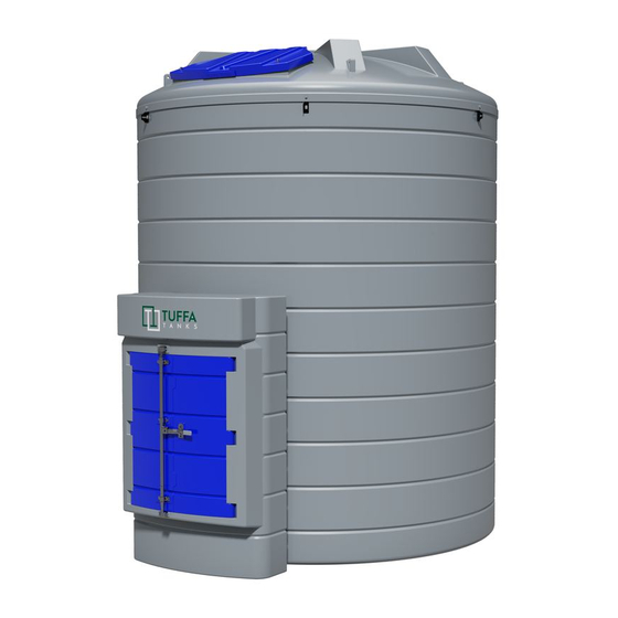
Page 6: Product Description
4. PRODUCT DESCRIPTION 4. Product description Tuffa AdBlue® Stations are designed solely for storage and dispensing of AdBlue®. The static bunded systems enable safe AdBlue® storage and dispensing in an outdoor environment. The high standard of specification ensures optimum safety and functionality. This product’s standard specification is not approved for the resale of AdBlue®. 4.1 Product identification The identification plate is located within the cabinet of each system and will detail the capacity, serial number, model number and year of manufacture. -
Page 7: Product Specification
4.PRODUCT DESCRIPTION 4.2 Product specification 1350SLBFS 2500HBFS 3500VBFS 6000VBFS 10000VBFS 15000VBFS ® ® ® ® ® ® AdBlue AdBlue AdBlue AdBlue AdBlue AdBlue Capacity 1350 litres 2500 litres 3500 litres 6000 litres 10000 litres 15000 litres Length 2680mm 2840mm Width 870mm 1520mm Diameter 2034mm 2580mm 2890mm 2860mm Height 1665mm 1630mm 2520mm... -
Page 8: Product Footprint
4. PRODUCT DESCRIPTION Product footprint 1350SLBFS AdBlue® 2500HBFS AdBlue®... - Page 9 4.PRODUCT DESCRIPTION 3500VBFS AdBlue® 6000VBFS AdBlue®...
- Page 10 4. PRODUCT DESCRIPTION 10000VBFS AdBlue® 15000VBFS AdBlue®...
-
Page 11: Transport & Storage
5. TRANSPORT & STORAGE 5. Transport & storage DO NOT TRANSPORT WITH LIQUID INSIDE THE TANK During transportation the flip lid and cabinet doors are secured by 1 x R clip. The R clip must be installed prior to transportation. Loading and off-loading must be carried out by a competent person using suitable rated and maintained equipment, either a forklift with extended forks/tines or a crane. If lifting slings are used, they must be attached to the lifting points as shown in the pictures below using a steel lifting eye insert. If lifting from below use a suitable rated forklift with extended forks. If lifting from above use a suitable rating lifting slings / chains. 1350SLBFSAD / 2500HBFSAD - Lift with main lifting eye highlighted in red in the image below or forklift from the side. 3500VBFSAD / 6000VBFSAD / 10000VBFSAD / 15000VBFSAD - Lift with x4 equal spaced lifting brackets as highlighted in red in the image below or forklift from one side using a ratchet strap to secure the tank to the forklift mast. 5. Tuffa AdBlue® Stations must never be pushed or rolled. During transport and storage, the flip lid or cabinet doors must be closed and secured. Loading, transport and storage areas must be smooth and free of sharp edges. -
Page 12: Installation & Commissioning
6. INSTALLATION & COMMISSIONING 6. Installation & commissioning 6.1 Installation guidelines The proprietor of the Tuffa AdBlue® Station is responsible for complying with all legal require- ments relating to the installation and use of this product, as well as the guidelines issued by local firefighting authorities and environmental authorities. Once the Tuffa AdBlue® Station has been received on site, check that no damage has oc- curred while in transit. Locate the tank in the desired location using either crane, forklift or rollers. 6.2 System installation System foundation The system must be installed and fully supported on a smooth levelled concrete base built in accordance with good building standards and engineering principles. It is recommended that tanks be installed on a concrete base at least 100mm thick. Please refer to diagram below: 6.3 System location The location of the system should be positioned by a road or passing with sufficient width, and loading capacity to accommodate a tanker delivering AdBlue®. Provision for the U-turn of a tanker should be considered. Potential obstacles in the form of tree branches, high voltage lines, or parked vehicles must be minimized. The space around the system should allow free and collision-free movement of served vehi- cles. Provision should be made to protect tank from impact damage. -
Page 13: Electrical Requirements
6. INSTALLATION & COMMISSIONING 6.4 Electrical requirements Only a suitably qualified electrician according to applicable regulations may work on the elec- tric wiring installation. The system components under service, maintenance, and repair work must be disconnected from the power supply before any work in undertaken. System power requirements: • 220 - 240 Volts, 50 Hz +/- 10% • 20 amp circuit breaker recommended • Power cable recommendation: 3 Core 2.5mm flex cable 6.5 Electrical wiring diagram 6.5.1 1350SLBFS AdBlue® / 2500HBFS AdBlue® – Key Switch... - Page 14 6. INSTALLATION & COMMISSIONING 6.5.2 3500VBFS AdBlue® / 6000VBFS AdBlue® / 10000VBFS AdBlue® / 15000VBFS AdBlue® – Key Switch...
-
Page 15: Operation Of The System
7. OPERATION OF THE SYSTEM Operation of the system The system and its components are intended for AdBlue® only and for the purposes de- scribed below. Use of this system in a means other than described below is regarded as mis-use of the system, the user of the system will be liable for any defects that occur due to its unintended use. 7.1 Using the system The operation and maintenance personnel must be suitably trained to use the system, the user must make sure they fully understand the operation and maintenance sections of this manual. 7.2 Summary of main parts 1350 / 2500... -
Page 16: Summary Of Main Parts 3500 / 6000 / 10000 / 15000
7. OPERATION OF THE SYSTEM 7.3 Summary of main parts 3500 / 6000 / 10000 / 15000... -
Page 17: Filling Adblue® Station
7. OPERATION OF THE SYSTEM 7.4 Filling AdBlue® Station 1. Filling should be performed only under constant supervision of an authorised person. 2. This tank can only be filled by a tanker equipped with a 2” female dry break coupling. 3. On 3500 / 6000 / 10000 / 15000 models before filling the tank with AdBlue®, please check the level of the tank and make note of the tank level before filling and ensure the high level alarm indicator functions correctly. 4. Fit tanker delivery hose to 2” dry break fill coupling on tank. 5. Engage tanker pump and begin to fill. Stop filling when desired amount has been dispensed into tank, or when high-level alarm sounds. 6. During the tanker fill always observe tank level gauge throughout the duration of the filling process. The tanker driver must observe the tank being filled at all times during this process. 7. Once complete disconnect delivery hose from tank coupling. 7.5 Dispensing AdBlue® into vehicle 1. Reset the flowmeter totalizer to 0 2. Activate pump using one of the following: Rocker switch, key switch, auto - operational nozzle holster 3. Remove nozzle from nozzle holster and insert the nozzle completely into the AdBlue® tank filler neck 4. Pull trigger on the nozzle to allow AdBlue® to flow into the vehicle AdBlue® tank 5. At this time the flowmeter counter will start recording the flow, continue refueling until... -
Page 18: Equipment Components
7. OPERATION OF THE SYSTEM 7.6 EQUIPMENT COMPONENTS 7.6.1 FMS GAUGE LEVEL (3500 | 6000 | 10000 | 15000) The Fuel Level Monitoring System is a 240v combined digital tank level indicator and bund and high-level alarm that is designed to provide both visual and audible alarms whenever a predetermined F. FMS WIRING DIAGRAM level in a storage tank is reached. The FMS gives a content readout in both litres and a percentage. A. FULL ALARM Activation of this alarm indicates that the tank is full. This alarm is shown through visual LED’s and audible siren. Note: This audible and visual alarm will remain triggered for a short period of time after it sounds. The audible can be muted using the mute button on the keypad. THE PUMP WILL CONTINUE TO DISPENSE IN THIS ALARM MODE. B. HIGH LEVEL ALARM Activation of this alarm indicates the tank has reached a high capacity and close attention must be paid to the diesel inside the tank. This alarm is shown through visual LED’s and audible... - Page 19 7. OPERATION OF THE SYSTEM 7.6.2 NOZZLE & INTEGRATED FLOWMETER (1350 | 2500) C. MISFILLING Premise A. INSTALLATION Mode with display of Partial and Total dispensed quantities The automatic nozzles are supplied ready for use. Operation The nozzle features a SWIVEL hose-end fitting (complete with O-ring) The “magnet switch” is a magnetic field within the filler necks of the useful for connecting to the supply hose. nozzle. This opens the magnet switch in the spout, so it is only possible to dispense from the tank where the magnet adaptor is installed. TO ENSURE PERFECT OPERATION, THE DEVICE MUST BE USED Attention TO DISPENSE FLUIDS WITH CHARACTERISTICS FALLING WITHIN Nozzles equipped with “magnet switch” work only in combination with THE FOLLOWING PARAMETERS: the “magnet adapter”. The “magnet adapter” is an option to be bought - Qmin .: 15 l/min - Qmax: 45 l/min separately. - Pmin. : 1,5 bar - Pmax: 3,5 bar D. PRELIMINARY CHECK Attention Warning During installation, use adequate sealants, being careful no residues Check the correct operation of the lock device, according to the following remain inside the hose.
- Page 20 7. OPERATION OF THE SYSTEM 1. General Total that cannot be reset (TOTAL) above the word total disappears, and the reset total is replaced by the 2. Resettable total (Reset TOTAL) general total. This situation is called standby and remains stable until the 5. Indication of total multiplication factor (x10 / x100 ) user operates the K24 again. 6. Indication of type of total, (TOTAL / Reset TOTAL); 7. Indication of unit of measurement of Totals: L=Litres Gal=Gallons 8. Indication of Flow Rate mode 9. Indication of unit of measurement of Partial: Qts=Quarts Pts=Pints L=Litres Gal=Gallons G1.1 PARTIAL RESET (NORMAL MODE) F1. USER BUTTONS The partial register can be reset by pressing the The METER features two buttons (RESET and CAL) which individually reset key when the meter is in standby, meaning perform two when the display screen shows the word “TOTAL”. main functions and, together, other secondary functions. After pressing the reset key, during reset, the Main functions performed display screen first of all shows all the lit-up digits - for the RESET key, resetting the partial register and Reset Total and then all the digits that are not lit up. - for the CAL key, entering instrument calibration mode Secondary functions At the end of the process, a display page is first of Used together, the two keys permit entering configuration mode where...
- Page 21 7. OPERATION OF THE SYSTEM the Totals (Reset or NON Reset) which are again displayed when exiting from the flow rate reading mode. To return to “Normal” mode, press the CAL key again. If one of the two keys RESET or CAL is accidentally pressed during the count, this will have no effect. H4.1 DISPLAY OF CURRENT CALIBRATION FACTOR AND ATTENTION RESTORING FACTORY FACTOR Even though in this mode they are not displayed, both the Reset Total and the General Total (Total) increase. Their value can be checked By pressing the CAL key while the appliance is in. after dispensing has terminated, returning to “Normal” mode, by Standby, the display page appears showing the quickly pressing CAL. current calibration factor used. If no calibration has ever been performed, or the factory setting has G2.1 PARTIAL RESET (FLOW RATE MODE) been restored after previous calibrations, the To reset the Partial Register, finish dispensing and following display page will appear: The word “Fact” wait for the Remote Display to show a Flow Rate of abbreviation for “factory” shows that the factory 0.0 as indicated in the illustration then quickly press calibration factor is being used.
- Page 22 7. OPERATION OF THE SYSTEM 5. After dispensing, wait a few minutes to make sure any air bubbles are ACTION DISPLAY eliminated from the sample container; only read the Real value at the end of this stage, during which the level in the container could drop. SHORT RESET key keying 6. Carefully follow the procedure indicated below The arrow changes direction. The operation can be repeated to alternate H4.2.1 IN FIELD CALIBRATION PROCEDURE the direction of the arrow. ACTION DISPLAY SHORT/LONG CAL key keying NONE The indicated value changes in the NEXT in Standby direction indicated by the arrow - one unit for every short CAL key keying - continually if the CAL key is kept pressed. The speed increase rises LONG CAL key keying by keeping the key pressed. If the The NEXT enters calibration mode, desired value is exceeded, repeat the...
- Page 23 7. OPERATION OF THE SYSTEM I. METER CONFIGURATION ACTION DISPLAY The METER feature a menu with which the user can select the main NONE measurement unit, Quarts (Qts), Pints (Pts), Litres (Lit), Gallons (Gal); METER in Standby The combination of the unit of measurement of the Partial register and that of the Totals is predefined a cording to the following table: LONG CAL KEY KEYING NEXT enters calibration mode, shows “CAL” and displays the calibration Combination Unit of Measurement Unit of Measurement factor being used instead of the partial. Partial Register Totals Register The words “Fact”and “User” indicate Litres (L) Litres (L) which of the two factors (factory or user) is currently being used. Gallons (Gal) Gallons (Gal) LONG RESET KEY KEYING Quarts (Qts)
- Page 24 7. OPERATION OF THE SYSTEM 7.6.3 FLOWMETER (FITTED TO 3500 | 6000 | 10000 | 15000) To change the UNSCREW THE NUT batteries, with REMOVE THE COVER (1) reference to the LOOSEN THE SCREW (2) exploded diagram positions, proceed REMOVE THE COVER (3) RIGHT SIDE as follows: CHANGE THE BATTERIES ASSEMBLE EVERYTHING BACK ON A. INTRODUCTION THE SEAL AROUND THE COVER Not suitable when used in a retail sale of AdBlue®. HOUSING AND TAKE CARE TO PLACE ATTENTION DO NOT OVER-TIGHTEN THE SCREW...
- Page 25 7. OPERATION OF THE SYSTEM B3. PROCEDURE TO ENTER THE CORRECTION FACTOR DIRECTLY Carefully follow the procedure indicated below: FORMULA Proper correction factor = current correction factor × (actual value/ display value) The Partial register positioned in the top part of the display indicates the quantity dispensed since the RESET button was last pressed. Example: Actual value 20.75 - The Reset Total register, positioned in the lower part of the display, Display value 18.96 indicates the quantity dispensed since the last Reset Total resetting. Current correction factor 1.000 The Reset Total cannot be reset until the Partial has been reset, while Proper correction factor 1.000×(20.75/18.96)=1.000×1.094=1.094 vice versa, the Partial can always be reset without resetting the Reset Total. The unit of measurement of the two Totals can be the same as the B4. MODIFY THE CORRECTION FACTOR IN FIELD Partial or else different according to the factory or user settings.
- Page 26 7. OPERATION OF THE SYSTEM After pressing the RESET button, during reset, the display screen first followed by all the switched-off segments. Finally it shows the display shows all the lit-up digits and then all the digits that are not lit up. page where the reset total is shown. C3. DISPENSING WITH THE FLOW RATE MODE DISPLAY It is possible to dispense fluids, displaying at the same time: •The dispensed Partial •The flow rate in [Partial Unit / minute] as shown on the following display page: At the end of the process, a display page is first shown with the Reset Partial and the Reset Total. Procedure for entering this mode: 1. Wait for the Remote Display to go to Standby, meaning the display screen shows “Total only” After a few moments, the Reset Total is replaced by the NON resettable. 2. Quickly press the CAL button. 3. Start dispensing The flow rate is updated every 0.7 seconds. Consequently, the display could be relatively unstable at lower flow rates. The higher the flow rate, the more stable the displayed value. C2. RESETTING THE RESET TOTAL The Reset Total resetting operation can only be performed after resetting WARNING the Partial register. The Reset Total can in fact be reset by pressing the The flow rate is measured with reference to the unit of measurement RESET button at length while the display screen shows “Reset Total” as of the Partial.
- Page 27 7. OPERATION OF THE SYSTEM To enter the configuration menu, proceed as follows: and, as an optional, it can have the Pulse OUT outlet to transmit impulses to a display repeater known as the “Pulse IN Remote Display”. 1. Wait for the Remote Display to go on Stand-by; 2. Press the CAL and RESET buttons at the same time and hold them down until the word “Unit” and the previously-set unit of measurement appear on the display (Litre/Litre in this example); 3. To move between submenus press the CAL button once quickly. For the “Remote Display Pulse In” to show the correct quantity of fluid, it must be configured with an “impulse weight” that is consistent with what D2. CONFIGURATION OF THE UNITS OF MEASUREMENT is being received from the Universal Remote Display Pulse in. To do The configuration menu for the units of measurement allows the user to this, the Remote Display must be configured in accordance with impulse select the partial unit of measurement between four available units: Quarts numbers by partial unit of measurement issued by the Universal Remote (Qt), Pints (Pt), Litres (L) and Gallons (Gal). Display with Pulse Out. The combination between the Partial register and the Total register units is Enter the configuration menu as shown previously. Press the CAL button preset according to the following table: to go to the Pulser inlet configuration submenu: the script “P_in” and the previously set number of impulses by unit of measurement will appear on the display. “10” on the display indicates that 10 impulses by partial unit of measurement must enter on the inlet. WARNING The partial unit of measurement of the Universal Remote Display Pulse In must be the same as that of the Universal Remote Display Pulse Out to Press the RESET button quickly to scroll through all the available which it is connected.
-
Page 28: Maintenance Of The Tuffa Tanks
8. MAINTENANCE OF THE TUFFA TANKS 8. Maintenance of the TUFFA TANKS Keep this manual stored in a place of use so it can be obtained for future reference. All persons who install, commission, maintain, and operate the system must be deemed competent by their employers and have the adequate knowledge and training required to carry out any required tasks which are recommended by this manual, it is recommended that any persons carrying out work on the system have fully read and understood the instructions set out by this manual. It is advised that no changes nor conversions with potential impact on safety may be performed on this system, any spare parts which are used must comply with the technical requirements which are defined in this manual or directly by the manufacturer. ATTENTION Please make sure prior to any maintenance work that power supply is turned OFF and that there is not an inadvertent chance to reconnect the system to power supply. WARNING System warranty will become void if any repairs are made by technicians not authorised by the manufacturer, the same applies to works with hazardous or potentially hazardous equipment. ATTENTION Do not use jet cleaners to clean the system. You can clean the system with water and household cleaners. Do not use an excessive amount of water when cleaning near any electrical items as this can cause a short circuit to occur potentially permanently damaging the equipment. 8.1 System maintenance tasks Activity Frequency of Task... -
Page 29: Inspection By Competent Person
8. MAINTENANCE OF THE TUFFA TANKS 8.2 System maintenance tasks Inspection by Competent Person Inspections should be undertaken by a competent person that is receiving a delivery of product on every fill prior to and whilst filling. This inspection should include: • The fill point arrangement for soundness and leaks • Any outlet valves should be checked for leaks and operation (open and close successfully) • The testing of contents gauge, any high level / overfill alarm and bund alarm. • If vents can be seen that they are clear and unblocked and free of debris. • A visual inspection around the tank with emphasis on the base of the tank. The inspection for plastic tanks should include any deformation of the surface of the tank i.e. excessive bulging, change in colour due to chemical attack, crazing or stress fractures. The inspection of steel tanks should include looking for evidence of rust and heavy corrosion, damp patches on seams & seam fractures. • Bund to be visually inspected for soundness and integrity, water, spilt product, or other debris. 8.3 Internal examination and cleaning Internal examinations should be undertaken by a competent person at appropriate intervals, as determined by the product used, and its cleanliness i.e. solids or water falling out of suspension. Entry into confined spaces should be carefully planned and supervised and should be subject to a strict procedures dependent on the substance stored, and in accordance with HSE requirements. -
Page 30: Troubleshooting
8. MAINTENANCE OF THE TUFFA TANKS 8.4 Troubleshooting Symptom Possible Causes Solutions No power 1. Local distribution board fuse 1. Check local distribution board RCD 2. Power cable damaged 2. Check condition of power cables 3. Power cable connection broken 3. Check power cable connections 4. - Page 31 8. MAINTENANCE OF THE TUFFA TANKS 8.4 Troubleshooting Symptom Possible causes solutions AdBlue® in bund cavity 1. Inner tank overfill 1. AdBlue® must be removed from the cavity as soon as possible 2. Pipework leaking in bund cavity 2. See point 1 3.
-
Page 32: Tank Maintenance Record
8. MAINTENANCE OF THE TUFFA TANKS 8.5 Tank maintenance record Date Description of works Comments Site representative / contractor details... - Page 33 8. MAINTENANCE OF THE TUFFA TANKS 8.5 Tank maintenance record Date Description of works Comments Site representative / contractor details...
-
Page 34: Adblue® Delivery Log
8. MAINTENANCE OF THE TUFFA TANKS 8.6 AdBlue® delivery log Date Description of works Comments Site representative / contractor details... - Page 35 8. MAINTENANCE OF THE TUFFA TANKS 8.4 AdBlue® delivery log Date Description of works Comments Site representative / contractor details...
-
Page 36: Warranty
9. WARRANTY 9. Warranty Subject to the conditions below, your product is supplied with a warranty against material defects in workmanship or materials from the date of delivery or invoice Tax point date, whichever is earliest for the following warranty period: PRODUCT WARRANTY PERIOD IF WARRANTY PERIOD IF REGISTERED NOT REGISTERED Bunded AdBlue® Station 10 years 5 years tanks ACCESSORIES WARRANTY PERIOD AdBlue® Station ancillary equipment 1 year Suction and delivery hoses 90 days The warranty is subject to the following conditions: To qualify for the extended warranty period this product must be registered and installed by a registered competent person in accordance with prevailing statutory requirements. The period of the warranty will commence from the date of delivery or invoice Tax point date, whichever is earliest. The warranty is provided to the original purchaser only. Proof of purchase and evidence of annual inspection by a registered competent person will be required in the event of a claim. To obtain the extended warranty period for your product, you must register the purchase and installation of your product with us within 21 days from date of purchase. To register, please complete and submit our registration form. Registration forms can be obtained and submitted online at www.tuffa.co.uk. Failure to register the purchase and installation of your product (or incomplete registration) within the 21 day period will mean that the shorter warranty period (above) only will apply to your product. During the warranty period, any component of your product which is proved to contain any material defect in workmanship or materials will be exchanged or repaired, at our sole discretion, by us free of charge for material or labour. In respect of your product, the warranty does not cover (and we will not accept responsibility for) any consumable items, any component which has not been manufactured by us (please refer to the manufacturer’s warranty supplied with the relevant component), fair wear and tear, or any fault: • in respect of any component not forming part of your product; or... -
Page 37: Contact
10. CONTACT | 11. GUARANTEE REGISTRATION • caused by alteration or repair by you or by a third party who is not one of our authorised repairers; or • caused by non-observance of either any applicable statutory requirement or any of the instructions contained in the installation and operating instructions appropriate to your product, and in this respect, we would draw particular attention to the fact that your product must not be used in conditions which are either below -17°C or which are above 35°C without protection from exposure to direct sunlight. Your product has been used only for the purpose for which it is designed, and that any terms and conditions held with your installer have also been adhered to. To the maximum extent permitted by UK law: • the warranty is given in lieu of all other warranties, express or implied by statute or common law, including implied warranties or conditions of satisfactory quality and fitness for a particular purpose, provided that this warranty is in addition to your legal rights in relation to goods that are faulty or not as described; and • we shall not in any circumstances be liable to you or any other party, whether in contract, tort (including for negligence and breach of statutory duty howsoever arising), misrepresentation (whether innocent or negligent), restitution or otherwise, for any special, indirect or consequential loss or damage. 10. Contact Tuffa UK Limited Tel: +44 (0) 1889 567700 Dovefields Industrial Estate Web: www.tuffa.co.uk Derby Road Email: sales@tuffa.co.uk Uttoxeter Staffordshire ST14 8SW 11. Guarantee registration To register your tank warranty please visit the link to our website as below. The guarantee card must be completed online within 21 days of the date of the tank delivery to the first purchaser (namely the person or entity buying direct from Tuffa UK Limited). - Page 38 NOTES...
- Page 39 NOTES...
Need help?
Do you have a question about the AdBlue 1350SLBFSAD and is the answer not in the manual?
Questions and answers