Table of Contents
Advertisement
Quick Links
INSTRUCTION MANUAL
TWO-WIRE TRANSMITTER ALARM
(dual or quad alarm trip)
BEFORE USE ....
Thank you for choosing M-System. Before use, please check
contents of the package you received as outlined below.
If you have any problems or questions with the product,
please contact M-System's Sales Office or representatives.
■ PACKAGE INCLUDES:
Two-wire transmitter alarm (body + base socket).............(1)
■ MODEL NO.
Confirm Model No. marking on the product to be exactly
what you ordered.
■ INSTRUCTION MANUAL
This manual describes necessary points of caution when
you use this product, including installation, connection and
basic maintenance procedures.
The M7EASDY is programmable using the PC configurator
software. For detailed information on the PC configuration,
refer to the M7CFG instruction manual. The M7CFG PC
Configurator Software is downloadable at M-System's web
site: http://www.m-system.co.jp.
POINTS OF CAUTION
■ CONFORMITY WITH EU DIRECTIVES
• This equipment is suitable for use in Measurement Cat-
egory I or II (output, transient voltage: 1500V), Installa-
tion Category II (transient voltage: 2500V), in Pollution
Degree 2 environment. Reinforced insulation (signal in-
put or output to power input: 300V) and basic insulation
(signal input to output: 300V) are maintained. Prior to
installation, check that the insulation class of this unit
satisfies the system requirements.
• Altitude up to 2000 meters.
• The equipment must be mounted inside a panel.
• Insert a noise filter for the power source connected to the
unit. TDK-Lambda Noise Filter Model RSAN-2006 or
equivalent is recommended.
• The equipment must be installed such that appropriate
clearance and creepage distances are maintained to con-
form to CE requirements. Failure to observe these re-
quirements may invalidate the CE conformance.
• The actual installation environments such as panel con-
figurations, connected devices, connected wires, may af-
fect the protection level of this unit when it is integrated
in a panel system. The user may have to review the CE
requirements in regard to the whole system and employ
additional protective measures to ensure the CE conform-
ity.
• Install lightning surge protectors for those wires connect-
ed to remote locations.
5-2-55, Minamitsumori, Nishinari-ku, Osaka 557-0063 JAPAN
Phone: +81(6)6659-8201 Fax: +81(6)6659-8510 E-mail: info@m-system.co.jp
MODEL
■ POWER INPUT RATING & OPERATIONAL RANGE
• Locate the power input rating marked on the product and
confirm its operational range as indicated below:
100 – 240V AC rating: 85 – 264V, 47 – 66 Hz,
approx. 5 – 8.5VA
24V DC rating: 24V ±10%, approx. 3W
■ GENERAL PRECAUTIONS
• Before you remove the unit from its base socket or mount
it, turn off the power supply and input signal for safety.
■ ENVIRONMENT
• Indoor use.
• When heavy dust or metal particles are present in the
air, install the unit inside proper housing with sufficient
ventilation.
• Do not install the unit where it is subjected to continuous
vibration. Do not subject the unit to physical impact.
• Environmental temperature must be within -5 to +55°C
(23 to 131°F) with relative humidity within 30 to 90% RH
in order to ensure adequate life span and operation.
• Be sure that the ventilation slits are not covered with ca-
bles, etc.
• Output code 2 and 3: For use in operations with all 4
relays normally energized, install the unit ensuring space
equivalent to its size at the left and right sides.
■ WIRING
• Do not install cables close to noise sources (relay drive
cable, high frequency line, etc.).
• Do not bind these cables together with those in which
noises are present. Do not install them in the same duct.
■ AND ....
• The unit is designed to function as soon as power is sup-
plied, however, a warm up for 10 minutes is required for
satisfying complete performance described in the data
sheet.
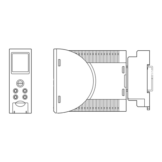
COMPONENT IDENTIFICATION
Body
LCD Display
Fixing Screw
(screw for attaching
the body to the
base socket)
M7EASDY
Base Socket
EM-7763 Rev.5 P. 1 / 9
Advertisement
Table of Contents

Subscribe to Our Youtube Channel
Related Manuals for M-system M7EASDY


Summary of Contents for M-system M7EASDY
- Page 1 • Locate the power input rating marked on the product and confirm its operational range as indicated below: Thank you for choosing M-System. Before use, please check 100 – 240V AC rating: 85 – 264V, 47 – 66 Hz, contents of the package you received as outlined below.
-
Page 2: Installation
22 (.87) 29 (1.14) 94 (3.70) 29.5 (1.16) 124 (4.88) [4 (.16)] (.31) • When mounting, no extra space is needed between units. EM-7763 Rev.5 P. 2 / 9 5-2-55, Minamitsumori, Nishinari-ku, Osaka 557-0063 JAPAN Phone: +81(6)6659-8201 Fax: +81(6)6659-8510 E-mail: info@m-system.co.jp... - Page 3 N.O. L1 OUTPUT 200Ω INPUT – MONITOR 50Ω – (1 – 5V DC) N.C. JACK CONFIGURATOR N.O. L2 OUTPUT U(+) POWER V(–) EM-7763 Rev.5 P. 3 / 9 5-2-55, Minamitsumori, Nishinari-ku, Osaka 557-0063 JAPAN Phone: +81(6)6659-8201 Fax: +81(6)6659-8510 E-mail: info@m-system.co.jp...
-
Page 4: Front View
M7EASDY ■ MONITOR MODE FRONT VIEW The M7EASDY starts operating in the Monitor Mode when the power supply is turned on. In this mode, the display is used to monitor present input LCD Display values and to confirm alarm setting. The front control but-... -
Page 5: Alarm Setting
+107.5%) and press Set button. from None (No average function), 4 samples, 8 samples, 5) Use Up-Down buttons to choose a corresponding Y value EM-7763 Rev.5 P. 5 / 9 5-2-55, Minamitsumori, Nishinari-ku, Osaka 557-0063 JAPAN Phone: +81(6)6659-8201 Fax: +81(6)6659-8510 E-mail: info@m-system.co.jp... -
Page 6: Alarm Latching
4) Press Mode button to save the setting and exit the Back Light setting. Whatever is this setting, a red backlight is maintained while the unit is in alarm conditions. EM-7763 Rev.5 P. 6 / 9 5-2-55, Minamitsumori, Nishinari-ku, Osaka 557-0063 JAPAN Phone: +81(6)6659-8201 Fax: +81(6)6659-8510 E-mail: info@m-system.co.jp... - Page 7 Trip Operation Select (L1, L2, L3, L4) Hi or Lo alarm trip Coil at Alarm Select (L1, L2, L3, L4) Energize or De-energize EM-7763 Rev.5 P. 7 / 9 5-2-55, Minamitsumori, Nishinari-ku, Osaka 557-0063 JAPAN Phone: +81(6)6659-8201 Fax: +81(6)6659-8510 E-mail: info@m-system.co.jp...
- Page 8 SER NO. : Serial number TAG NO. : Tag name Tag No. Setting Alarm Test Mode Execute Testing (L1, L2, L3, L4) EM-7763 Rev.5 P. 8 / 9 5-2-55, Minamitsumori, Nishinari-ku, Osaka 557-0063 JAPAN Phone: +81(6)6659-8201 Fax: +81(6)6659-8510 E-mail: info@m-system.co.jp...
-
Page 9: Wiring Instructions
1) Terminal wiring: Check that all cables are correctly con- nected according to the connection diagram. M-System offers a series of lightning surge protector for 2) Power input voltage: Check voltage across the terminal protection against induced lightning surges. Please contact 10 –...
Need help?
Do you have a question about the M7EASDY and is the answer not in the manual?
Questions and answers