Table of Contents
Advertisement
Quick Links
61" Model:
Model
5901013
72" Models:
Zero-Turn Rider
5901011
Mower Deck
5900591
5900592
Zero-Turn Rider
5901282
w/ Mower Deck
5901283
This manual is available in Spanish. For a copy, contact your Ferris dealer or www.ferrisindustries.com.
Este manual está disponible en Español. Para obtener una copia, póngase en contacto con su
Description
IS5100ZC33D, Zero-Turn Rider w/ Caterpillar Diesel & 61" Mower Deck
IS5100ZC33D, Zero-Turn Rider w/ Caterpillar Diesel
5100/72, 72" Side Discharge Mower Deck
5100/72RD, 72" Rear Discharge Mower Deck
IS5100ZC33D72, Zero-Turn Rider w/ Caterpillar Diesel & 72" Side Mower Deck
IS5100ZC33D72RD, Zero-Turn Rider w/ Caterpillar Diesel & 72" Rear Discharge
Mower Deck
distribuidor Ferris o www.ferrisindustries.com.
OPERATOR'S
MANUAL
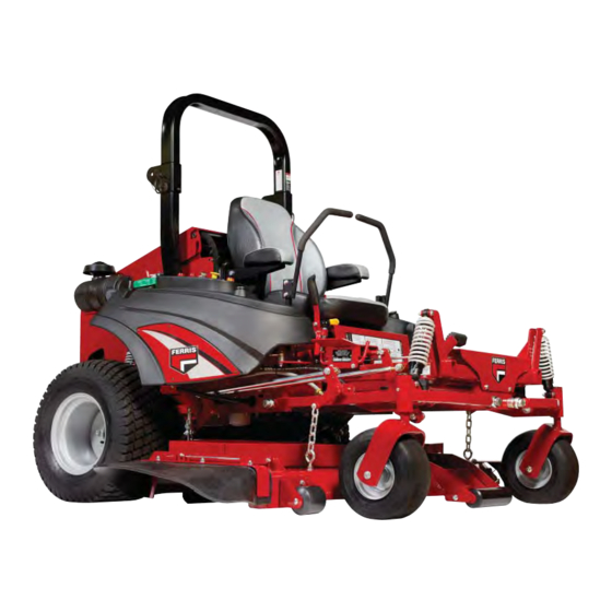
IS5100Z Series
Zero-Turn Riding Mower
5102954
Rev G
Advertisement
Table of Contents
Troubleshooting

Related Manuals for Ferris IS5100ZC33D72RD


Summary of Contents for Ferris IS5100ZC33D72RD
- Page 1 IS5100ZC33D72RD, Zero-Turn Rider w/ Caterpillar Diesel & 72” Rear Discharge Mower Deck This manual is available in Spanish. For a copy, contact your Ferris dealer or www.ferrisindustries.com. Este manual está disponible en Español. Para obtener una copia, póngase en contacto con su distribuidor Ferris o www.ferrisindustries.com.
- Page 2 Briggs & Stratton Power Products Group, LLC. Copyright © 2016 Briggs & Stratton Corporation Milwaukee, WI, USA. All rights reserved. FERRIS is a trademark of Briggs & Stratton Corporation Milwaukee, WI, USA. Contact Information: Briggs & Stratton Power Products Group, LLC.
-
Page 3: Table Of Contents
Table of Contents Operator Safety ..........2 Troubleshooting, Adjustments & Repair ..34 Identification Numbers ..........11 Troubleshooting the Rider ........34 Safety Alert Symbol & Signal Words ....11 Troubleshooting the Mower ........35 Safety Decals ............12 Troubleshooting Common Cutting Problems ..36 Safety Icons ............13 Hood Latch Operation ...........37 Safety Interlock System ........13 Floor Pan Removal &... -
Page 4: Operator Safety
Operator Safety Operating Safety Congratulations on purchasing a superior-quality piece of lawn and garden equipment. Our products are designed and manufactured to meet or exceed all industry standards for safety. Do not operate this machine unless you have been trained. Reading and understanding this operator’s manual is a way to train yourself. - Page 5 Operator Safety Slope Operation Operation on slopes can be dangerous. Using the unit on a slope that is too steep where you do not have adequate wheel traction (and control) can cause sliding, loss of steering, control, and possible rollover. You should not operate on a slope greater than a 5.4 foot rise over a 20 foot length (15 degrees).
- Page 6 Operator Safety Roll Bar Use Keep the roll bar in the raised position and fasten the seat belt. There is no roll over protection when the roll bar is down! Do not jump off if the mower tips (it is safer to be secured by the seat belt with the roll bar raised.) Lower the roll bar only when necessary (such as to temporarily clear a low overhanging obstacle) and...
- Page 7 Operator Safety Fuel and Maintenance Always disengage all drives, shutoff the engine, and remove the key before doing any cleaning, refueling, or servicing. Gasoline and its vapors are extremely flammable. Do not smoke while operating or refueling. Do not add fuel while engine is hot or running.
- Page 8 Operator Safety Read these safety rules and follow them closely. Failure to obey these rules could result in loss of control of unit, severe personal injury or death to you, or bystanders, or damage to property or equipment. This mowing deck is capable of amputating hands and feet and throwing objects. The triangle in text signifies important cautions or warnings which must be followed.
- Page 9 Operator Safety 23. Use care when approaching blind corners, shrubs, 5. Use extra care with grass catchers or other trees or other objects that may obscure vision. attachments. These can change the stability of 24. To reduce fire hazard, keep unit free of grass, the unit.
- Page 10 Operator Safety EMISSIONS where there is an open flame, such as in a water heater. Allow unit to cool before storing. 1. Engine exhaust from this product contains 5. Shut off fuel while storing or transporting. Do not chemicals known, in certain quantities, to cause store fuel near flames or drain indoors.
- Page 11 Operator Safety leaks. Make sure all hydraulic fluid connections To maintain operator roll over protection and roll bar are tight and all hydraulic hoses and lines are in effectiveness: good condition before applying pressure to the • If a ROLL BAR becomes damaged for any reason, system.
- Page 12 Operator Safety WARNING INSPECT BUCKLE & LATCH Failure to properly inspect and maintain the seat belt can cause serious injury or death. INSPECTION AND MAINTENANCE OF THE ROLL BAR SEAT BELT • The seat belt like the ROLL BAR, needs to be periodically inspected to verify that the integrity has not been compromised through normal machine use, misuse, age degradation,...
-
Page 13: Identification Numbers
Operator Safety Identification Numbers Safety Alert Symbol & Signal Words Tractor The alert symbol is used to identify safety Identification Tag information about hazards that can result in personnal injury. A signal word (DECAL, WARNING, or CAUTION) is used with the alert symbol to indicate the likelihood and the potential severity of the injury. -
Page 14: Safety Decals
Operator Safety Safety Decals Before operating your unit, read the safety decals. The cautions and warnings are for your safety. To avoid a personal injury or damage to the unit, understand and follow all safety decals. WARNING If any safety decals become worn or damaged, and cannot be read, order replacement decals from your local dealer. -
Page 15: Safety Icons
Operator Safety Safety Icons Safety Interlock System This unit is equipped with safety interlock switches. These safety systems are present for your safety, do not attempt to bypass safety switches, and never tamper with safety devices. Check their operation regularly. Operational SAFETY Checks Test 1 —... -
Page 16: Features & Controls
Features & Controls release the lever to lock the seat in position. Features and Controls F. (S/N: 2016098451 & Above) Removable Floor Plate: The floor plate can be removed for easy access to the mower deck. To remove the plate, remove the black knob and tilt the floor pan up and then remove from the machine. - Page 17 Features & Controls Glow Plug Indicator: Lamp that indicates that the glow plugs are heating. Hold the ignition key in the “HEAT” position until indicator lamp turns off, then turn the key to start. C. PTO (Power Take Off) Switch: The PTO switch engages and disengages the mower.
-
Page 18: Operation
Operation Checks Before Starting Operation • Check that crankcase is filled to full mark on General Operating Safety dipstick. See the engine Operators Manual for instructions and oil recommendations. Before first time operation: • Check the radiator fluid level. See engine •... -
Page 19: Priming The Fuel System
Operation Priming the Fuel System Priming the fuel system fills the fuel filters and removes any air bubbles from the fuel system. This must be performed before the first use, after any fuel filter maintenance or if the fuel system is run dry. WARNING Fuel leaked or spilled onto hot surfaces or electrical components can cause a fire. -
Page 20: Starting The Engine
Operation Stopping the Rider & Engine WARNING 1. Returning the ground speed control levers to the If you do not understand how a specific control middle position will stop tractor movement. Pivot functions, or have not yet thoroughly read the the levers outward and lock them in neutral. -
Page 21: Zero Turn Driving Practice
Operation Zero-Turn Driving Practice Smooth Travel The lever controls of The lever controls of the Zero Turn rider are the Zero Turn rider responsive, and learning to gain a smooth and are RESPONSIVE. efficient control of the rider’s forward, reverse, and turning movements will take some practice. - Page 22 Operation Practice Turning Around a Corner Practice Turning In Place While traveling forward allow one handle to gradually To turn in place, “Zero Turn,” gradually move one return back toward neutral. Repeat several times. ground speed control lever forward from neutral and one lever back from neutral simultaneously.
-
Page 23: Mowing
Operation The amount of grass you are able to cut in one pass Mowing is also effected by the type of mowing system you are 1. Engage the parking brake. Make sure that the using (for example, broadcasting with side discharge PTO switch is disengaged, the ground speed decks can process a much larger volume of grass control levers are locked in the NEUTRAL position... -
Page 24: Mowing Methods
Operation When and How Often to Mow The time of day and condition of the grass greatly affect the results you’ll get when mowing. For the best results, follow these guidelines: 1. Mow when the grass is between three and five inches high. - Page 25 Operation Proper Mulching Mulching consists of a mower deck which cuts and recuts clippings into tiny particles and which then blows them down INTO the lawn. These tiny particles decompose rapidly into by-products your lawn can use. UNDER PROPER CONDITIONS, your mulching mower will virtually eliminate noticeable clippings on the lawn surface.
-
Page 26: Pushing The Rider By Hand
Operation Pushing the Rider by Hand Attaching a Trailer The maximum weight of a towed trailer should be DO NOT TOW RIDER less than 300 lbs (138kg). Secure the trailer with a Towing the unit will cause hydraulic pump appropriately sized clevis pin (A, Figure 9) and clip and wheel motor damage. -
Page 27: Raise & Lower The Roll Bar
Operation Raise & Lower the Roll Bar To lower the roll bar: 1. Pull the hair pin clips (A, Figure 10) out of the retainer pins (B). 2. Push or pull the top of the roll bar (C) forward against the rubber stops (D) and remove the retainer pins (B). -
Page 28: Storage
Operation Storage WARNING Temporary Storage (30 Days Or Less) Never store the unit, with diesel fuel in engine Remember, the fuel tank will still contain some fuel, so or fuel tank, in a heated shelter or in enclosed, never store the unit indoors or in any other area where poorly ventilated enclosures. -
Page 29: Regular Maintenance
Regular Maintenance Maintenance Maintenance Schedule & Procedures The following schedule should be followed for normal care of your rider and mower. You will need to keep a record of your operating time. Determining operating time is easily accomplished by observing the hour meter. RIDER MAINTENANCE ENGINE MAINTENANCE Before Each Use... -
Page 30: Checking/Adding Fuel
Regular Maintenance Checking / Adding Fuel To add fuel: 1. Remove the fuel cap (A, Figure 12). 2. Fill the tank to the bottom of the fill tube. This will leave room in the tank for fuel expansion. Refer to your engine manual for specific fuel recommendations. -
Page 31: Check / Add Engine Oil
Filter Part Number: 5021357 NOTE: Removing the oil filter from the filter base will drain the oil reservoir. Have a suitable container ready to catch any spilled oil. Ferris recommends this be a dealer-only service item. Figure 15. Hydraulic Oil Reservoir 1. -
Page 32: Check Engine Coolant Level
Regular Maintenance Check Engine Coolant Level WARNING If engine is warm, DO NOT remove radiator cap. Escaping steam can cause burns. Never remove the radiator cap or radiator reservoir cap while the engine is hot or running. Severe thermal burns or injury can occur by escaping steam or hot coolant. -
Page 33: Lubrication
Regular Maintenance Lubrication Lubricate the unit at the locations shown in Figure 19 through 23. Grease: Use grease fittings when present. Disassemble parts to apply grease to moving parts when grease fittings are not installed. Not all greases are compatible. Red Grease (P/N Figure 21. -
Page 34: Cleaning The Battery & Cables
Regular Maintenance Cleaning the Battery and Cables (Note: The tractor equipped with a maintenance-free BCI58 battery) 1. Disconnect the cables from the battery, negative cable first (B, Figure 24). 2. Remove the battery and clean the compartment with a solution of baking soda and water. 3. -
Page 35: Servicing The Mower Blades
Regular Maintenance Servicing the Mower Blades 1. Blades should be sharp and free of nicks and dents. If not, sharpen blades as described in following steps. 2. To remove blade for sharpening, use a 1” wrench on the flats of the spindle shaft while removing the blade mounting bolt with a 15/16”... -
Page 36: Troubleshooting, Adjustments & Repair
Troubleshooting, Adjustment & Repair Troubleshooting WARNING While normal care and regular maintenance will To avoid serious injury, perform maintenance extend the life of your equipment, prolonged or on the tractor or mower only when the engine constant use may eventually require that service be is stopped and the parking brake engaged. -
Page 37: Troubleshooting The Mower
Troubleshooting, Adjustment & Repair Troubleshooting the Rider Continued PROBLEM CAUSE REMEDY Engine runs, but rider will not drive. Hydraulic dump valve(s) in “open” Turn dump valve(s) clockwise to close. position. Torque to 80-120 in.lbs. (9-13.5 Nm) Belt is broken. See Belt Removal and Replacement. Drive belt slips. -
Page 38: Troubleshooting Common Cutting Problems
Troubleshooting, Adjustment & Repair Troubleshooting Common Cutting Problems PROBLEM CAUSE REMEDY Streaking Blades are not sharp. Sharpen your blades. Blades are worn down to far. Replace your blades. Engine speed is too slow. Always mow at full throttle. Ground speed is too fast. Slow down. -
Page 39: Hood Latch Operation
Troubleshooting, Adjustment & Repair Hood Latch Operation This unit is equipped with a hood latch that must be released prior to opening the hood. 1. Pull the hood latch (A, Figure 28) towards the rear of the machine to release the hood latch. 2. -
Page 40: Mowing Height Adjustment
Troubleshooting, Adjustment & Repair Mowing Height Adjustment The cutting height adjustment pin (A, Figure 31) controls the mower cutting height. The cutting height is adjustable between 1-1/2” (3,8 cm) and 6” (15,2 cm) in 1/4” (0,64 cm) increments. 1a. Models S/N: 2016098450 & Below: Press the hydraulic mower lift switch (B) to the right (away from the operator’s seat) to raise the mower deck until it locks into the 6”... -
Page 41: Ground Speed Control Lever Adjustment
Troubleshooting, Adjustment & Repair Ground Speed Control Lever Adjustment The control levers can be adjusted in three ways. The alignment of the control levers, the placement of the levers (how close the ends are to one another) and the height of the levers can be adjusted. Handle Alignment Loosen the mounting hardware (A, Figure 33) and pivot the lever(s) (C) fore or aft to align with each... -
Page 42: Neutral Adjustment
Troubleshooting, Adjustment & Repair Neutral Adjustment If the tractor “creeps” while the ground speed control levers are locked in NEUTRAL, then it may be necessary to adjust the control linkage. NOTE: Perform this adjustment on a hard, level surface such as a concrete floor. 1. -
Page 43: Parking Brake Adjustment
Troubleshooting, Adjustment & Repair Parking Brake Adjustment FRONT 1. Disengage the PTO, stop the engine, block the front wheels, remove the ignition key, and engage 2" - 2-1/8" the parking brake. (5,0 - 5,4cm) 2. Locate the upper brake spring (A, Figure 37) through the opening under the fuel tanks. -
Page 44: Rear Tire Camber Adjustment
Troubleshooting, Adjustment & Repair 5. Retighten the two (2) 1/2-20 X 3” bolts and the (2) Rear Tire Camber Adjustment 1/2-20 X 1-3/4” bolts. The rubber bushings in the cast A-arms may stretch 6. Reinstall the tire. and wear with time and adversely affect the angle that the rear tire runs against the ground. -
Page 45: Suspension Adjustment
Troubleshooting, Adjustment & Repair Suspension Adjustment The shock assembly can be adjusted to vary the amount of pre-load applied to the springs. This allows the operator to maintain the ride height. Use less pre-load for light weight operators. Use more pre-load for heavy weight operators. To adjust the spring pre-load: 1. -
Page 46: Deck Lift Rod Timing Adjustment
Troubleshooting, Adjustment & Repair Deck Lift Rod Timing Adjustment 1. Park machine on a flat, level surface. Disengage Inner Rod the PTO, stop the engine and engage the parking brake. Rear tires must be inflated to 18 psi (1,24 bar); front tires to 25 psi (1,72 bar). 2. -
Page 47: Deck Leveling Adjustment
Troubleshooting, Adjustment & Repair Deck Leveling Adjustment NOTE: Before adjusting the deck level, the deck lift rod timing must be checked and/or adjusted. 1. Park machine on a flat, level surface. Disengage the PTO, stop the engine and engage the parking brake. -
Page 48: Mower Deck Drive Belt Replacement S/N: 2016528079 & Below
Troubleshooting, Adjustment & Repair Mower Deck Drive Belt Replacement S/N: 2016528079 & Below To avoid damaging belts, DO NOT PRY BELTS OVER PULLEYS. 1. Park the tractor on a smooth, level surface such as a concrete floor. Disengage the PTO, engage the parking brake, turn off the engine, and remove the ignition key. - Page 49 Troubleshooting, Adjustment & Repair approximately 5 minutes to break in the belt. Check the Mower Belt Tensioner Spring Length 1. Lower the mower deck to its lowest cutting position. 2. Measure the coil length (E, Figure 50) of the mower belt tensioner spring (A). The measurement should equal the measurement as indicated in the chart.
-
Page 50: Mower Deck Drive Belt Replacement S/N: 2016528080 & Above
Troubleshooting, Adjustment & Repair Mower Deck Drive Belt Replacement S/N: 2016528080 & Above To avoid damaging belts, DO NOT PRY BELTS OVER PULLEYS. 1. Park the unit on a smooth, level surface such as a concrete floor. Disengage the PTO, engage the parking brake, turn off the engine, and remove the ignition key. -
Page 51: Pto Clutch Drive Belt Removal
Troubleshooting, Adjustment & Repair PTO Clutch Drive Belt Removal 1. Park the tractor on a smooth, level surface such as a concrete floor. Disengage the PTO, engage the parking brake, turn off the engine, and remove the ignition key. 2. Release the hood latch and raise the hood until it locks in place. -
Page 52: Pump Drive Belt Removal & Replacment
Troubleshooting, Adjustment & Repair Pump Drive Belt Removal S/N: 2016098450 & Below 1. Park the tractor on a smooth, level surface such as a concrete floor. Disengage the PTO, engage the parking brake, turn off the engine, and remove the ignition key. 2. -
Page 53: Above
Troubleshooting, Adjustment & Repair Gearbox Maintenance Check Gearbox Oil Level 1. Remove fill plug (A, Figure 55) on gearbox. 2. Once plug is removed, oil should seep out of fill plug hole. If no oil drains out, fill with SAE 80-90 weight gear oil until oil starts to seep from hole, then replace fill plug. -
Page 54: Deck Shut Down Module
Troubleshooting, Adjustment & Repair Deck Shut Down Module This unit is equipped with a deck shut down module that will automatically shut down the mower deck if the engine looses oil pressure or begins to overheat. What to do if the deck shuts down during operation: •... -
Page 55: Battery Service
Troubleshooting, Adjustment & Repair Battery Service battery is fully charged when the cells are gassing freely at low charging rate and less than 0.003 change in specific gravity occurs over a three hour WARNING period. Keep open flames and sparks away from the Jump Starting With Auxiliary (Booster) Battery battery;... - Page 56 Troubleshooting, Adjustment & Repair WARNING For your personal safety, use extreme care when jump starting. Never expose battery to open flame or electric spark – battery action generates hydrogen gas which is flammable and explosive. Do not allow battery acid to contact skin, eyes, fabrics, or painted surfaces.
-
Page 57: Specifications
Specifications Specifications TRANSMISSIONS: PUMP: NOTE: Specifications are correct at time of printing Hydro-Gear PW-1ACC (LH) (S/N: All) and are subject to change without notice. Hydro-Gear PW-1DCC (RH) (S/N: All) WHEEL MOTOR: ENGINE: Parker TF0405UB080AADD S/N: 2016098450 & Below (LH & RH) 33 Gross HP¹... - Page 58 Notes...
- Page 59 ABOUT YOUR WARRANTY Warranty service is available only through FERRIS Authorized Service Dealers. This warranty covers only defects in materials or workmanship. It does not cover damage caused by improper use or abuse, improper maintenance or repair, normal wear and tear, or stale or unapproved fuel.
- Page 60 OPERATOR’S MANUAL IS5100Z Series Zero-Turn Riding Mower...
Need help?
Do you have a question about the IS5100ZC33D72RD and is the answer not in the manual?
Questions and answers