
Related Manuals for Acer Studio MMP3400


Summary of Contents for Acer Studio MMP3400
- Page 1 Studio MMP3400 Service Guide Service guide files and updates are available on the ACER/CSD web; for more information, please refer to http://csd.acer.com.tw PRINTED IN TAIWAN Get other manuals https://www.bkmanuals.com...
- Page 2 Revision History Please refer to the table below for the updates made on Studio MMP3400 service guide. Date Chapter Updates Get other manuals https://www.bkmanuals.com...
- Page 3 Copyright Copyright © 2009 by Acer Incorporated. All rights reserved. No part of this publication may be reproduced, transmitted, transcribed, stored in a retrieval system, or translated into any language or computer language, in any form or by any means, electronic, mechanical, magnetic, optical, chemical, manual or otherwise, without the prior written permission of Acer Incorporated.
- Page 4 Conventions The following conventions are used in this manual: Denotes actual messages that appear SCREEN MESSAGES on screen. NOTE Gives bits and pieces of additional information related to the current topic. WARNING Alerts you to any damage that might result from doing or not doing specific actions.
- Page 5 DIFFERENT part number code to those given in the FRU list of this printed Service Guide. You MUST use the list provided by your regional Acer office to order FRU parts for repair and service of customer machines.
- Page 6 Get other manuals https://www.bkmanuals.com...
-
Page 7: Table Of Contents
Studio MMP3400 System Block Diagram ........3... - Page 8 VIII Get other manuals https://www.bkmanuals.com...
-
Page 9: System Specifications
Chapter 1 System Specifications Features Below is a brief summary of the Studio MMP3400’s feature: Main Chip : ESS ES6461 • Main Memory : 16MB SDRAM, 8Mx16 x1pcs. • Serial Flash : 2MB SPI Flash. • Stereo Audio DAC: ES64641 build in •... - Page 10 System setup • USB 2.0 HOST port x 1 and Mini USB Device port x1 in Rear I/O. • Video output support • Component video up to 1080i • CVBS –PAL system • HDMI—480p up scaling to 1080P • Audio output support •...
-
Page 11: Studio Mmp3400 System Block Diagram
Studio MMP3400 System Block Diagram Component Component 16MB SDRAM 16MB SDRAM (8Mx16)x1pcs (8Mx16)x1pcs Composite Composite 2MB SPI Flash 2MB SPI Flash Audio Audio Audio L/R Audio L/R filter filter SATA HDD SATA HDD SPDIF SPDIF ES6461 ES6461 GL830 GL830 Mini-USB... -
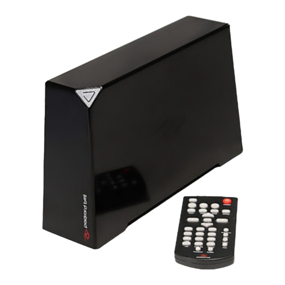
Page 12: Your Studio Mmp3400 Tour
Your Studio MMP3400 tour Appearance Item Description Connection LIght Red - On • Flashing - Hard drive activity • Off - Standby • High Definition Video Out This connector provides a high definition video signal. The YPbPr cable must be connected to this port. - Page 13 Removet Control Function depends on active selection: Button Movie Music Picture Settings HOME Display the main menu VOL - Decrease volume VIDEO Go to the Video screeen PHOTO Go to the Photo screen DIRECTION KEYS Go up, down, left, right. Left arrow: go up one directory.
- Page 14 Function depends on active selection: Button Movie Music Picture Settings AUDIO/EQ Switch audio track Adjust the music Adjust the music during playback playback effect playback effect during music slideshow INFO Displays file information (e.g. size, format, etc.) during playback THUMBNAILS Displays image preview BACK Return to playlist...
-
Page 15: Disassembly/Reassembly Requirements
Chapter 2 Machine Disassembly and Replacement This chapter contains step-by-step procedures on how to disassemble and reassemble the Studio MMP3400 for maintenance and troubleshooting. Disassembly/Reassembly Requirements To disassemble or reassemble the computer, you need the following tools: Wrist grounding strap and conductive mat for preventing electrostatic discharge •... -
Page 16: Disassembly Process
Disassembly Process This section guide you on how to disassemble the Studio MMP3400 when you need to perform system service of to replace a replaceable parts. The list below are the list of screws used in the Studio MMP3400. Main Screw List... -
Page 17: Removing The Base
Carefully release the latches and carefully lift up the outer casing. Removing the Base See “Removing the Outer Casing” on page 8. Remove the one screw (B) securing the base to the housing. Step (Quantity) Color Torque Silver 6.0 kgf-cm Chapter 2 Get other manuals https://www.bkmanuals.com... -
Page 18: Removing The Hard Drive
Release the latches and carefully lift up the housing. Removing the Hard Drive See “Removing the Outer Casing” on page 8. See “Removing the Base” on page 9. Carefully slide out the metal shielding. Remove the three screws (B) securing the hard drive to the housing. Chapter 2 Get other manuals https://www.bkmanuals.com... -
Page 19: Removing The Fan Module
Step (Quantity) Color Torque Silver 6.0 kgf-cm Slide out the hard drive and remove it from the housing. NOTE: To prevent damage to device, avoid pressing down on it or placing heavy objects on top of it. Removing the Fan Module See “Removing the Outer Casing”... - Page 20 Remove the three screws (C) securing the fan module to the housing. Step (Quantity) Color Torque Silver 1.5 kgf-cm Remove the fan module from the housing. Chapter 2 Get other manuals https://www.bkmanuals.com...
-
Page 21: Removing The Ir Board
Removing the IR Board See “Removing the Outer Casing” on page 8. See “Removing the Base” on page 9. See “Removing the Hard Drive” on page 10. See “Removing the Fan Module” on page 11. Disconnect the IR cable from the IR board connector. Remove the one screw (C) securing the LED bracket. -
Page 22: Removing The Main Board
Remove the one screw (C) securing the IR board to the housing. Step (Quantity) Color Torque Silver 1.5 kgf-cm Remove the IR board from the housing. Removing the Main Board See “Removing the Outer Casing” on page 8. See “Removing the Base” on page 9. See “Removing the Hard Drive”... - Page 23 Remove the one screw (D) near the HDMI connector. Step (Quantity) Color Torque Silver 6.0 kgf-cm Carefully lift up and remove the main board from the housing. Note: Circuit board >10 cm² has been highlighted with the yellow rectangle as above image shows. Please detach the Circuit boards and follow local regulations for disposal.
-
Page 24: Reassembly Process
Reassembly Process This section guide you on how to reassemble the Studio MMP3400 after maintenance and troubleshooting. Main Board Reassembly Reconnect the IR cable into the main board. Replace the main board into the housing. Replace the one screw (D) near the HDMI connector. -
Page 25: Ir Board Reassembly
Replace main board and secure it to the housing with the four screws (B). Step (Quantity) Color Torque Silver 6.0 kgf-cm IR Board Reassembly See “Main Board Reassembly” on page 16. Replace the IR board and secure it to the housing with the one screw (C). Step (Quantity) Color... -
Page 26: Fan Module Reassembly
Replace the LED bracket and secure it to the housing with the one screw (C). Step (Quantity) Color Torque Silver 1.5 kgf-cm Reconnect the IR cable into the IR board connector CN1. Fan Module Reassembly See “Main Board Reassembly” on page 16. See “IR Board Reassembly”... - Page 27 Replace the fan module and secure it to the housing with the three screws (C). Step (Quantity) Color Torque Silver 1.5 kgf-cm Reconnect the fan module cable to the connector CN4 on the main board. Chapter 2 Get other manuals https://www.bkmanuals.com...
-
Page 28: Hard Drive Reassembly
Hard Drive Reassembly See “Main Board Reassembly” on page 16. See “IR Board Reassembly” on page 17. See “Fan Module Reassembly” on page 18. Slide the hard drive until the connector on the hard drive is securely connected to the SATA connector on the main board. -
Page 29: Base Reassembly
Replace the metal shielding to the hard drive. Base Reassembly See “Main Board Reassembly” on page 16. See “IR Board Reassembly” on page 17. See “Fan Module Reassembly” on page 18. See “Hard Drive Reassembly” on page 20. Replace the housing into the base until the latches clicks into place. Chapter 2 Get other manuals https://www.bkmanuals.com... -
Page 30: Outer Casing Reassembly
Secure the housing with the one screw (B). Step (Quantity) Color Torque Silver 6.0 kgf-cm Outer Casing Reassembly See “Main Board Reassembly” on page 16. See “IR Board Reassembly” on page 17. See “Fan Module Reassembly” on page 18. See “Hard Drive Reassembly” on page 20. See “Base Reassembly”... - Page 31 Secure the outer casing to the housing with the two screws (A). Step (Quantity) Color Torque Black 4.5 kgf-cm Replace the rubber foot to cover one of the screw. Chapter 2 Get other manuals https://www.bkmanuals.com...
- Page 32 Chapter 2 Get other manuals https://www.bkmanuals.com...
-
Page 33: Chapter 3 Troubleshooting
Chapter 3 Troubleshooting This is a list of possible situations that may arise during the use of your Studio MMP3400, and it gives easy answers and solutions to these questions. No display on TV Make sure the Studio is plugged in and turned on. -
Page 34: How To Upgrade Firmware
How to upgrade firmware Put the firmware into the USB flash drive and plug this USB flash drive into MMP3400. Power on MMP3400 and go to SETTINGS menu. Chapter 3 Get other manuals https://www.bkmanuals.com... - Page 35 In the SETTINGS menu, select PREFERENCES and use navigation key to highlight Firmware Upgrade. Then press RIGHT key to highlight UPGRADE and press ENTER. System will pop out a confirmation message. Press LETF key to highlight YES in red and then press ENTER.
- Page 36 System will start to update the firmware. After the system completes the upgrade, it will power on automatically. Press POWER key on the remote control to power on the system. After the system is boot up, go to “SETTINGS-->PREFERENCES. Use the navigation key to highlight Default.
-
Page 37: Main Board Layout
Chapter 4 Connector Locations and Board Layout Main Board Layout SKT2 SKT4 SKT5 SKT1 SKT3 Item Description Item Description Processor ES6461SAB component video SDRAM NT5SV8M16FS-6K composite video+ audio L/R Flash MX25L1605DM SKT1 HDMI connctor Scaler ES7109S SKT3 Mini-USB connector Controller GL830-MX SKT4 USB A Type EEPROM AT93C46DN... -
Page 38: Rear I/O Connectors
Rear I/O Connectors Composite Jack Audio R/L USB A Type SPDIF Component Jack DC Jack HDMI Mini USB IR Board Placement Chapter 4 Get other manuals https://www.bkmanuals.com... -
Page 39: Fru (Field Replaceable Unit) List
DIFFERENT part number code from those given in the FRU list of this printed Service Guide. You MUST use the local FRU list provided by your regional Acer office to order FRU parts for repair and service of customer machines. - Page 40 HDMI CABLE 1.5M C.A HDMI CABLE WITH 1.5M 50.T1901.005 IR BAORD CABLE C.A. P7 C2 L170 50.T1901.001 IR/LED HOLDER HLDR LED MMP3400 42.T1901.001 TOP COVER ASSY TOP COVER MMP3400 60.T1901.002 REAR COVER ASSY BOTTOM COVER MMP3400 60.T1901.003 TOP SHIELD BRACKET BRKT TOP SHIELD MMP3400 33.T1901.001 LOWER COVER...
- Page 41 HDD 2TB 3.5” 5400RPM SATA WD GP500M HDD 2TB WD WD20EADS-22R6B0 GP KH.02K08.001 WD20EADS-22R6B0 GP HDD 3.5” 1000GB 7200RPM SATA HDD 1TB SGT ST31000528AS 7.2KR KH.01K01.007 SEAGATE SEAGATE ST31000528AS LF HDD 1TB 3.5” 7200RPM SATA HGST HDD 1TB HGST HDT721010SLA360 KH.01K07.002 SATURN HDT721010SLA360 HDD 1TB 3.5”...
- Page 42 Chapter 5 Get other manuals https://www.bkmanuals.com...
-
Page 43: Index
Index appearance block diagram disassembly process Disassembly Requirements Features field replaceable unit list ir board placement main board layout Main screw list rear i/o connectors reassembly process remote control System Block Diagram System block diagram Troubleshooting view left Get other manuals https://www.bkmanuals.com... - Page 44 Get other manuals https://www.bkmanuals.com...
Need help?
Do you have a question about the Studio MMP3400 and is the answer not in the manual?
Questions and answers