
Related Manuals for SKF IF-105

Summary of Contents for SKF IF-105
- Page 1 IF-105 user interface (Original operating and maintenance instructions) IF1051AEN.doc 03.01.2013 Rev. 1A...
-
Page 2: Table Of Contents
3.3.2 Pressure alarm, MonoFlex and DuoFlex lubrication systems..................9 3.3.3 Pulse alarm, ProFlex lubrication system .........................9 3.3.4 Alarm from SKF Doser monitor -doser operation indicator ..................9 3.3.5 Alarm from the air pressure switch of the grease spray system ................10 3.3.6 Warning message for pump change (doubled pumping center/Dualset)..............10 3.4 Manual operation.................................. -
Page 3: General Information
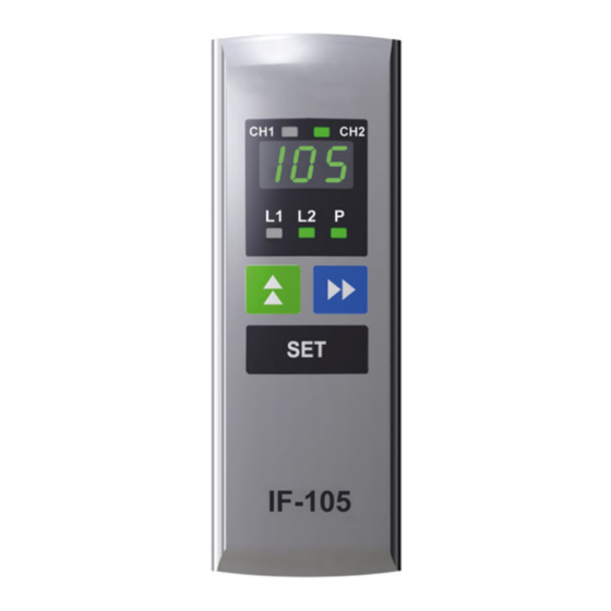
1 General information IF-105 is the user interface for the internal control unit of SKF Maxilube hydraulic part and for the SKF ST-1240-IF control center. Lubrication programming, alarm resetting and lubrication event monitoring can be performed with the user interface. -
Page 4: Led-Signals For Channels
2.1 LED-signals for channels Note! LED-signals CH1 and CH2 for lubrication channels are in use only in systems with two channels. LED-signal Description Red LED-signal is lit, when channel 1 is in alarm mode. Green LED-signal is lit, when channel 1 is in normal mode. LED-signal is blinking when channel 1 is selected on the display. -
Page 5: Buttons
2.3 Buttons Note! The buttons affect only the channel which is selected on the display. Button Description In normal mode, the button is used to browse set values on the display. In setting mode, the button is used to change the value on the display. ... -
Page 6: Operation
3 Operation 3.1 Normal mode 3.1.1 Functions Display power saving mode In normal mode, the display shifts to power saving mode when no buttons have been used for ten (10) minutes. In power saving mode only the decimal points are blinking on the display. Lubrication events are performed according to the set values. -
Page 7: Phase Codes For Normal Mode And Alarm Mode
(line pressure is not low enough when pressurization phase starts) (Alarm, High, Pressure) Alarm from doser operation indicator (SKF Doser monitor). The code is displayed only if SKF Doser monitors are in use. (Alarm, Indicator) Alarm from the air pressure switch of the grease spray system. -
Page 8: Normal Mode Displays, Monoflex And And Duoflex Lubrication Systems
3.1.3 Normal mode displays, MonoFlex and and DuoFlex lubrication systems Normal mode displays, which show the set values for the lubrication program, can be browsed with the -button. Display codes change in the following order when -button is pressed. Display code Description The lubrication channel selected on the display. -
Page 9: Normal Mode Displays, Proflex Lubrication System
3.1.4 Normal mode displays, ProFlex lubrication system Normal mode displays, which show lubrication program set values, can be browsed with the -button. Display codes change in the following order when -button is pressed. Display code Description The lubrication channel selected on the display. Press the SET-button to go to another channel when the code is displayed. -
Page 10: Pressure And Pulse Displays For Lines
3.1.5 Pressure and pulse displays for lines Pressure transmitter operation In pressure transmitter operation, line pressure displays can be selected with the -button. Pressing the button will show the pressure display for line 1 first. Code P1 and the pressure display for line 1 are displayed in turns. Pressing the button again will show the pressure display for line 2. -
Page 11: Low Level Alarm
The SKF Doser monitors are in use when factory settings parameter LGI has been set in status YES. An alarm will be triggered when the SKF Doser monitor does not recognize doser operation during a lubrication cycle. Code AIn is displayed. Lubrication continues normally despite the alarm. This feature is different from other alarms. -
Page 12: Alarm From The Air Pressure Switch Of The Grease Spray System
HL in status OFF • automatically when 60 minutes have elapsed since going into manual operation mode • restart SKF Maxilube hydraulic part or SKF ST-1240-IF control center • In manual operation mode SET-button is used to: start pumping •... -
Page 13: Settings
4 Settings 4.1 General Set values are lubrication channel basic values, for example lubrication cycle and maximum pressurization time. Set values are channel specific. All settings are password-protected. 4.2 Entering password Select the code for the setting to be changed on the display with the -button. Press the SET-button. -
Page 14: Lubrication Cycle
Protection class 5.2 Symbols IF-105 Abbreviation Description Interface 105: model 6 Contact information Oy SKF Ab P.O. Box 80 (Teollisuustie 6) FI-40951 MUURAME FINLAND Tel. +358 207 400 800 Fax. +358 207 400 899 www.skf.com IF1051AEN.doc 03.01.2013 Rev. 1A 12 (12)
Need help?
Do you have a question about the IF-105 and is the answer not in the manual?
Questions and answers