Table of Contents
Advertisement
Quick Links
Advertisement
Table of Contents

Related Manuals for D-Link DSC-6620


Summary of Contents for D-Link DSC-6620
-
Page 2: Table Of Contents
Schedule Video Recording with Motion Detection........123 Appendix......................126 Frequently Asked Questions............126 How to PING Your IP Address ............129 Reset and Restore ................131 External I/O Port ................131 Technical Specifications..............135 Contacting Technical Support..............137 Time Zone Table ..................138 Warranty ......................140 Registration ....................143 D-Link Systems, Inc. -
Page 3: Contents Of Package
DCS-6620 User’s Manual Package Contents Package Contents D-Link SECURICAM DCS-6620 PTZ Internet Camera Remote Control 12V AC Power Adapter A/V Cables Category 5 Ethernet Cable Camera Stand Quick Installation Guide Installation software and manual on CD If any of the above items are missing, please contact your reseller. -
Page 4: Introduction
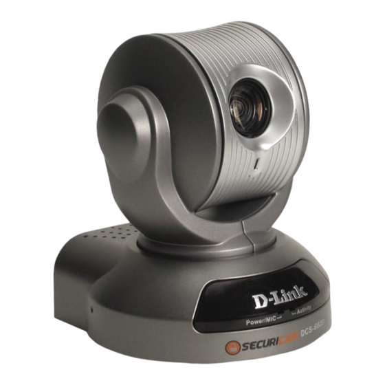
Introduction Introduction The D-Link SECURICAM Network DCS-6620 PTZ (Pan, Tilt, and Zoom) Internet Camera is a full featured surveillance system that connects to an Ethernet, Fast Ethernet or broadband Internet connection to provide remote high-quality 2-Way Full Duplex audio, and 10x optical and 10x digital zoom forgreaterclarityanddetailfromyourrecordings.TheDCS-6620isthelatestproductaddedtothe... - Page 5 D-Link product provided herein is suitable for the end-user’s intended use under the applicable laws of his or her state. D-Link disclaims any liability whatsoever for any end-user use of the D-Link product, which fails to comply with applicable state, local, or federal laws.
-
Page 6: Connections
The DCS-6620 PTZ Internet Camera has an internal microphone. However, you have the option of using an external microphone by plugging it into the microphone connector. A/V Out Plug the included A/V cable into the A/V out connector to use the DCS-6620 with a television or VCR. D-Link Systems, Inc. - Page 7 Attachment socket for the Camera Stand Located on the bottom panel of the DCS-6620, the socket is used to connect the camera stand to the PTZ Internet Camera by attaching the screw head on the camera stand to the PTZ Internet Camera. D-Link Systems, Inc.
- Page 8 Zooms in to display a specific area. Zoom Out: Zooms out to display a larger area. Auto-Patrol: Enables the Auto-Patrol function. Auto-Pan: Pans the camera one full cycle. Center: Centers the camera lens. Stop: Stops the movement of the camera during pan. D-Link Systems, Inc.
-
Page 9: Hardware Installation
Attach the camera stand to the PTZ Internet Camera and station it for your application. There is a hole located in the base of the camera stand allowing the PTZ Internet Camera to be mounted to the ceiling, or any wall securely. D-Link Systems, Inc. -
Page 10: Installation Wizard
(this function may be disabled in the Windows operating system), access the CD from Windows My Computer and click on the autorun.exe program to access the installation menu shown below: Install Software Click D-Link Systems, Inc. - Page 11 DCS-6620 User’s Manual Installation Wizard Install Wizard Click Please wait while the InstallShield Wizard prepares to install. Next Click D-Link Systems, Inc.
- Page 12 Click Next Select the Program folder that Setup will add program icons to.You may type a new folder name, or select one from the existing folders list. Next Click Please wait while the Installation Wizard is installed. D-Link Systems, Inc.
- Page 13 (see page 130 for the location of the reset hole). The LED on the front of the camera will begin blinking alternately. When it stops the blinking cycle continue to hold in the reset button for about 10 seconds. D-Link Systems, Inc.
- Page 14 DCS-6620, in this example it is: http://192.168.0.120.Your DCS-6620 may have a different IP Address. If a window appears asking to install a Verisign certificate for authentication Click Yes.This allows the proprietary MPEG-4 video stream to be recognized by Internet Explorer. D-Link Systems, Inc.
-
Page 15: Installation Wizard Screen
Remove: Click to remove the selected camera(s) from the network. Uncheck Click to uncheck all selected cameras. All: Links to Click to view all of the selected cameras. For each individual camera selected, Selected an individual Internet browser will appear. Devices: D-Link Systems, Inc. - Page 16 Advanced > Network screen (page 39) when configuring the camera via a Web Browser. Click Next and then Apply to save the configured settings. Users can click Previous to modify changes or mistakes. D-Link Systems, Inc.
- Page 17 Click the Reset to Default tab to reset the camera’s settings to factory defaults. About Click About to display the current version and date of the Installation Wizard. Exit Click the Exit tab to exit the Installation Wizard screen. D-Link Systems, Inc.
-
Page 18: Enabling Upnp Tm For Windows ® Xp
Use the following steps to enable UPnP (Universal Plug and Play) settings only if you are running Windows XP. If you are running Windows 2000, UPnP is not available. Go to Start >Settings. Control Panel Click Add or Remove Click Programs D-Link Systems, Inc. - Page 19 DCS-6620 User’s Manual Enabling UPnP for Windows ® Add/Remove Windows Click Components The following screen will appear: Networking Services Select Details Click Select Universal Plug and Play Click D-Link Systems, Inc.
- Page 20 DCS-6620 User’s Manual Enabling UPnP for Windows ® Next Click Please wait while Setup configures the components. Finish Click D-Link Systems, Inc.
- Page 21 (in this example, 198.168.0.146). After you click on the DCS-6620-146 icon, your Internet browser will automatically be opened to the IP Address of the DCS-6620, in this example it is: http://192.168.0.120. Your DCS-6620 may have a different IP Address. D-Link Systems, Inc.
-
Page 22: Installing Ip Surveillance Software
AVI file export Motion detection for each camera To install the IP surveillance software, click on Install IP surveillance Software on the CD included with the PTZ Internet Camera. The Welcome screen appears: Next Click D-Link Systems, Inc. - Page 23 Installing IP surveillance Software Click Please read the Software Licensing Agreement and click yes if you wish to accept the agreement. Click “No” to exit the installation. Next Click Enter your name and company information and then click “Next”. D-Link Systems, Inc.
- Page 24 DCS-6620 User’s Manual Installing IP surveillance Software Select the destination directory. Click Next Select the program folder the software will be installed into. Next Click D-Link Systems, Inc.
- Page 25 DCS-6620 User’s Manual Installing IP surveillance Software Click Next Finish Click The installation is complete. D-Link Systems, Inc.
-
Page 26: Testing The Dcs-6620
The window in the center of your browser is the camera image window. You should now see a video image and hear the audio over your computer speakers from the DCS-6620. If you are having problems please consult the FAQ section of this manual (page 126). D-Link Systems, Inc. -
Page 27: Security
Administrator has access to the management of the PTZ Internet Camera. This procedure should be done as soon as possible since the security features of the PTZ Internet Camera will not be enabled until the Administrator Password is defined. D-Link Systems, Inc. -
Page 28: Using And Configuring The Dcs-6620 With A Router
Using and Configuring the DCS-6620 with a Router D-Link’s DCS-6620 is a versatile and cost effective PTZ Internet Camera offering both video and audio monitoring. It can also serve as a powerful surveillance system in security applications. The DCS-6620 can be used with any wired or wireless router. This section explains how to view the camera from either the Internet or from inside your internal network. - Page 29 Viewing the Video on the browser to test the connection Click on the Configuration button on the left side of the display. Scroll to the bottom of the Network Configuration page to display the ports used by HTTP and Streaming audio and video. D-Link Systems, Inc.
- Page 30 Router Set-Up and Installation The following steps generally apply to any router that you have on your network. The D-Link DI-624 is used as an example to clarify the configuration process. Configure the initial settings of the DI-624 by following the steps outlined in the DI-624 Quick Installation Guide.
- Page 31 Virtual Server function on the DI-624 router. The Virtual Server ports used by the camera must be opened through the router for remote access to your camera. Virtual Server is accessed by clicking on the Advanced tab of the router screen. D-Link Systems, Inc.
- Page 32 Enter valid ports in the Virtual Server section of your router Please make sure to check the box on this line to enable settings D-Link Systems, Inc.
- Page 33 Web server port 80. To access from a computer on your local (home) network, simply enter the local IP Address of the Camera followed by a colon and the port number (e.g., http://192.168.0.120:83). Viewing the DCS-6620 Remotely D-Link Systems, Inc.
-
Page 34: Using The Dcs-6620 With An Internet Browser
Using the IP surveillance software with the DCS-6620. Open your Internet Explorer Web browser and enter the IP address for your PTZ Internet Camera. An example address is 192.168.0.120, but your address may differ. D-Link Systems, Inc. - Page 35 “-” sets the aperture smaller, and “+” sets the aperture bigger. Auto Pan: Pans the camera one full cycle. Stop: Stops movement of the camera during pan. Auto Patrol: Enables the Auto Patrol feature, please see page 53. D-Link Systems, Inc.
- Page 36 The image from the DCS-6620 should be visible from the Home page on your computer monitor. There are two buttons on the left side of the Home page: Client Settings and Configuration. Click on the Client Settings button to change settings related to the connection. Click Client Settings D-Link Systems, Inc.
- Page 37 JPEG images get periodically updated from the server according to the “Frame rate” settings. Talk Button Control Style Allows the User to determine whether to “click once and talk” or “push to talk”. Click the Home tab to return to the DCS-6620 Home page. D-Link Systems, Inc.
- Page 38 The Advanced tab is the default screen in Configuration and Network is the default screen under Advanced. Click Network Any changes made to these settings will require the system to restart . Make sure every field is correct before clicking on Apply. D-Link Systems, Inc.
- Page 39 2nd SMTP account name: The user name for the second SMTP server. The password used to log into the second e-mail account. (The 2nd SMTP password: password will appear as dots instead of entered characters.) D-Link Systems, Inc.
- Page 40 Note that the 2nd FTP server will only be used if the 1st FTP is unavailable. If image upload to the 1st FTP is successful, no attempts will be made to connect to the 2nd FTP server. 2nd FTP server port: The port to access the backup FTP server. D-Link Systems, Inc.
- Page 41 Consult with your network administrator or your Internet Service Provider (ISP) if you do not have the necessary information. If you cannot connect to the camera, refer to page 130 for camera reset and restore factory settings procedures. D-Link Systems, Inc.
- Page 42 With the DCS-6620, you can setup your DDNS service and the DCS-6620 will automatically update your DDNS server every time it receives a different IP address. Depending on the service, this update may take a few hours. D-Link Systems, Inc.
- Page 43 UPnP enabled PTZ Internet Camera. If your operating system is UPnP enabled, the device will be easier to configure. If you do not want to use the UPnP functionality, it can be disabled by unselecting “Enable UPnP”. Apply Click to make changes effective D-Link Systems, Inc.
- Page 44 “Fix bit rate” and select the desired bandwidth. Video codec type: It can be either MJPEG or MPEG4. In MJPEG mode, the video frames are independent. MPEG4 consumes much less network bandwidth than MJPEG. D-Link Systems, Inc.
- Page 45 Horizontally rotate the video. Check options both if the Network Mirror: Camera is installed upside down. Improve efficiancy Check this option to improve efficiency in the multi-user environment in the multi-user when running in the low bandwidth environment. environment: Apply Click to make changes effective D-Link Systems, Inc.
- Page 46 In this mode, the User can only talk to the server. Simplex- Talk only: Simplex- Listen only: In this mode, the User can only listen from the server. Disable: In this mode, the audio is disabled in both directions. D-Link Systems, Inc.
- Page 47 The faster frame rate in a slow network will blur the images. You may also try to choose 352x240/352x288 in size option for better images or 704x480/704x576 for larger image size. Because the network has burst constraints and everyone’s environment is not the same, any poor connection will impair normal performance. D-Link Systems, Inc.
- Page 48 Configuration > Advanced > Image Setting Click Image Setting Click the Image Setting button from the Configuration screen to access additional settings that affect how the video image appears. D-Link Systems, Inc.
- Page 49 Checking this box will assist in seeing objects in poor Low lux mode: illuminative environments. Apply when the DCS-6620 is aiming outdoors. Adjusting Auto tracking white balance: the 9 levels of white levels can help the camera to capture video with correct colors. D-Link Systems, Inc.
- Page 50 Configuration > Advanced > Motion Detection Click the Motion Detection button from the Configuration screen to access settings that effect how the DCS-6620 PTZ Internet Camera can serve as a security device by recording only when motion is detected. Click Motion Detection D-Link Systems, Inc.
- Page 51 (note: remember that you can have up to 3 windows selected for motion detection). You can return to the DCS-6620 Home Page and the monitored window will not be visible, but the red frame will show on the home page when motion is detected. D-Link Systems, Inc.
- Page 52 Select a value between -5 and +5, -5 being the slowest setting. Select the speed at which the camera will pan during auto Auto Pan/Patrol Speed: patrol. Select a value between 1 and 5, 1 being the slowest setting. D-Link Systems, Inc.
- Page 53 “Enable IR control”, “Dwelling time” and “Patrol selection”. In other words, after changing these settings, and the “Save” button is not clicked, the new setting of the camera will not take effect. Apply Click to make changes effective D-Link Systems, Inc.
- Page 54 This allows multiple visitors to share the same account of different levels. The Permission for I/O Control Permission for PTZ Control options (Digital In/Digital Out) and provided for each account. Some users may need to be prohibited from controlling your attached security devices. D-Link Systems, Inc.
- Page 55 (once a password has been set). Check this option to shut off the LED at the base of the Turn off the LED camera. This will prevent anyone from observing the indicator: operation of the PTZ Internet Camera. D-Link Systems, Inc.
- Page 56 Assign the IP address or domain name of the timeserver. NTP server: Leaving the text box blank will let DCS-6620 connect to default time servers. Time zone: Used to adjust the hour of time servers for local settings. Apply Click to make changes effective D-Link Systems, Inc.
- Page 57 DCS-6620 User’s Manual Using the DCS-6620 with an Internet Browser Configuration > Tools > Applications Click on the Applications button to access the Applications settings from the Tools menu. D-Link Systems, Inc.
- Page 58 An active, named motion window must be checked for motion detection to be possible. Check and save this option to reset the external device at Reset output: the digital output back to the original state. D-Link Systems, Inc.
- Page 59 “video@20020102030405.jpg” means the JPEG image was captured at 4 minutes and 5 seconds after 3 o’clock, January 2nd, A.D. 2002. If the suffix is omitted, the file named “video.jpg” on the external FTP server will be refreshed at the specified interval. D-Link Systems, Inc.
- Page 60 IP address of the DCS-6620. Click Apply under Calibrate to restore them camera’s factory lens position. This means that the camera will be recalibrated to the default center to position to recover from any external forces that may have affected it. D-Link Systems, Inc.
- Page 61 Click on the Log button to access a system log of system activity from the Status menu. The content of the log file reveals useful information about the current configuration and connection logged after the DCS-6620 boots up. Click Log D-Link Systems, Inc.
- Page 62 Configuration > Help Click on the Help tab to access descriptions of the particular function you need help with. The help screen is organized in the order of the tabs and then each menu item under that tab. D-Link Systems, Inc.
-
Page 63: Record Snapshots To Your Ftp Server With Motion Detection
Enter in a window name. Adjust the “Sensitivity” and “Percentage” levels according to the local environment. The highest sensitivity and lowest percentage provides the most sensitive setting. Click on save to enable the activity display. D-Link Systems, Inc. - Page 64 fill in the Domain name or IP address of your external FTP server such as ftp://dlink.com or ftp://123.123.123.1. (The server name and IP address will vary depending on the user.) The following user settings must be correctly configured for remote access. D-Link Systems, Inc.
- Page 65 firewall. For detailed information about each setting, please refer to Configuration > Advanced > Network in the section titled “Using the DCS-6620 With an Internet Browser” (page 39). Click the apply button when finished. D-Link Systems, Inc.
- Page 66 Click “Send snapshots by FTP” and check “FTP put snapshots with date and time suffix” Click the “Apply” button to save the settings. Click the apply button when finished.You are now able to record snapshots to your FTP server when motion detection is triggered. D-Link Systems, Inc.
-
Page 67: Using Ip Surveillance Software
Put the installation disk into your CD-ROM, and it will run automatically. If it does not, open “My Computer” and double click on the CD-ROM icon. Next the installation menu will appear. Click “Install Software”. The following window will appear. Click IP surveillance D-Link Systems, Inc. - Page 68 Using IP surveillance Software Installing the IP surveillance Software (continued) Click Next The “License Agreement” window below will appear. Please read the following license agreement carefully. Click “Yes” to accept this agreement and proceed with the installation. Click Yes D-Link Systems, Inc.
- Page 69 Enter your user name and company name and then click “Next” to continue. Click Next You must setup the administrator’s password in order to proceed. Input and confirm your password in the window shown in below. Click “Next” to continue. Click Next D-Link Systems, Inc.
- Page 70 figure below. You can change the installation directory by clicking “Browse…” Click Next Select a program folder to install the application software and then click “Next”, which is shown in the figure below. Click Next D-Link Systems, Inc.
- Page 71 After checking all the setup information in the window shown below, click “Next” to start the installation of the application software. Click Next Click “Finish”, in the window shown below, to finish installation. The program is now installed on your computer. Click Finish D-Link Systems, Inc.
-
Page 72: Launcher
After passing authentication, users will be able to use all the functions. If users want to leave the computer, it is possible to lock the Launcher for security reason. When Launcher is locked, the user will need to pass authentication again to see the popup menu. Below is the login window: D-Link Systems, Inc. - Page 73 When this item is selected, Launcher will enter lock mode. In lock mode, whenever users want to invoke the menu, a dialog asking for ID and password will appear. The interface for this dialog is covered in the previous section. D-Link Systems, Inc.
- Page 74 Exit Exits Launcher. If users choose this option, Launcher will show a message box prompting to confirm if users really want to exit, and warn users that exiting Launcher will also close Monitor and Playback. D-Link Systems, Inc.
-
Page 75: Monitor Program
Multiple recording modes: Event-driven, Scheduled, and manual recording for each camera. Intelligent database index modes: indexing by sharp time tag, time interval, and motion detected events. Just-in-time snapshot AVI export Motion detection with 3 alert windows for each camera D-Link Systems, Inc. - Page 76 In this area, you can see the video of the selected channel in the display frame. The number of the display frames in the video area depends on the layout chosen by the user. You can also use convenient controls to alter the video display. D-Link Systems, Inc.
- Page 77 You need to login the first time when you start the Launcher. The authentication window is shown below. If you do not have an account, the monitor tool will not execute. You must log in as admin (administrator) to use this application. Enter the password for the administrator. D-Link Systems, Inc.
- Page 78 You will need the admin (administrator) privilege in order to run the configuration. Once you click “Configuration Menu > Camera Configurations” for setting each camera, all recording processes will be stopped with a warning window popped up in advance to keep you informed. D-Link Systems, Inc.
- Page 79 Webpage Camera Selections The Layout of the Configuration In the local settings, shown below, three main functionalities are provided: Insert new History of all camera to cameras in the list the list Delete camera from the list D-Link Systems, Inc.
- Page 80 Once added, you will see the IP address of the camera and also the port that is opened on the camera (port 80 in this example), so that the images can be viewed from the browser The selected camera has been added to the selection list. D-Link Systems, Inc.
- Page 81 Clicking on one camera in the history list will insert the camera into the camera list. The historical camera list is shown below. Historical camera list Alert and Recording Settings Alert Settings Recording Settings D-Link Systems, Inc.
- Page 82 Record # secs. after event Recording will last for the limited time after the alert event has been invoked. Media Type You can specify which media type you want to record, Video, Audio, or both. D-Link Systems, Inc.
- Page 83 “SAVE” button in each corresponding page in order to save the settings to the cameras.There are different “SAVE” buttons for changing the settings of the local IP surveillance system and the remote Video Server / PTZ Internet Camera series product respectively. D-Link Systems, Inc.
- Page 84 You can activate the global settings window from “Configuration Menu > Global Settings...” shown above. All recording processes will be stopped when activating the global settings window, indicated by a warning window popped up in advance to keep you informed. D-Link Systems, Inc.
- Page 85 (on a First In First Out (FIFO) basis) when “Cycle Recording” has been checked. Alert Sound You can load a custom *.wav file for the sound of alert triggering.You can also select from the sound file in Windows. D-Link Systems, Inc.
- Page 86 Once it has been checked, the status bar in each channel showing date, location, connection, and recording time will be shown in both display frame mode and full screen mode. Location (channel number + camera name) Remote Time 0 day 00:01 Connection Time (Day:Hour:Min) Recording Time (Day:Hour:Min) D-Link Systems, Inc.
- Page 87 Backup Location Select window. After you have set your backup settings in the global settings window, you can backup recorded data by clicking “Backup” in the Configuration Menu, as seen below: D-Link Systems, Inc.
- Page 88 This means that this application software supports real-time recording with and without real-time monitoring for the dedicated video channel. Blink With the motion detection mechanism set in the DCS-6620, the light of the corresponding channel will blink once the motion event is triggered. D-Link Systems, Inc.
- Page 89 This section depicts the method of how to show the video of a specific channel in a display window. Step 1: Move the mouse cursor to the display window shown below Mouse cursor Display window Location hint Video 1 D-Link Systems, Inc.
- Page 90 Press and hold the left mouse button, and then move the cursor to a display window in the video area, which is shown below. Note that the cursor will change according to the area in order to indicate whether the area is droppable or not. Video 1 Droppable area Not droppable area D-Link Systems, Inc.
- Page 91 When the cursor shape changes to an arrow-shape over the trashcan, release the left mouse button. The video in the corresponding display window will disappear. All operations above are shown in the figure on the following page. D-Link Systems, Inc.
- Page 92 4 camera layout 6 camera layout 1 camera layout 16 camera layout 9 camera layout 13 camera layout D-Link Systems, Inc.
- Page 93 When you choose the one-camera layout or four-camera layout, the “Page up” and “Page down” buttons will be shown in the left-bottom corner of the video area. You can use these two buttons to switch the pages, as shown in the figure below. Use to switch between cameras. D-Link Systems, Inc.
- Page 94 The position that each video channel is in for every layout will be saved for the next time the layout is selected. Back to previous Back layout. Input/Output Control Tools Pan/Tilt control Alert Message Digital Input/ Digital Output D-Link Systems, Inc.
- Page 95 DI and also trigger the camera by DO switch Set digital output to LOW Set digital output to HIGH No connection When the color of a DI/DO number is gray, that means the video has not yet been connected to a camera. D-Link Systems, Inc.
- Page 96 02:41:00 PM in Motion Window 2 and Motion Window 3, for camera #1. If the message “PM 02:41:56=>DI #1” is listed, that means there is an alert triggered by the DI, for camera #1, at 02:41:56 PM . D-Link Systems, Inc.
- Page 97 Minimize This section will describe some other miscellaneous functions of the icons shown above. These functions are: Quit By clicking this button, IP surveillance will be closed with the latest settings saved. Minimize Minimize the Monitor application. D-Link Systems, Inc.
- Page 98 This section will describe the common control functions, shown above, which are depicted by the small icons. These functions only apply to the currently selected channel. These functions are: Volume Control Click on this button to adjust your volume settings. D-Link Systems, Inc.
- Page 99 Click on the printer icon to print the current image to your default printer. Trashcan You can drag and drop the video channel to the Trashcan to close the video connection with the DCS-6620. Status Bar Local time Software name Current login user Login time Software version D-Link Systems, Inc.
-
Page 100: Scheduling
Individual schedule for each video channel Supports up to 9 preset schedule schemes for each video channel Automatic period recording Invoke Scheduler This section discusses the method of how to invoke the scheduler. Start the Scheduler Schedule Tool D-Link Systems, Inc. - Page 101 Go to the configuration menu and click on “Scheduler” to launch the scheduler. The Layout and Functionalities Introduction The layout of the scheduler and its components, shown below, will be described. Part 1 Part 2 Part 3 Part 4 D-Link Systems, Inc.
- Page 102 The Functionalities of Configuration Components The four main parts of the scheduler have been briefly described in the section above. Parts 1-4 will be described in detail in the following section IP address Location Video channel D-Link Systems, Inc.
- Page 103 The corresponding changes for the markers on the week time-line will be automatically added to the hour time-lines, which is shown above. You can also mark and unmark the plotted bar by clicking and dragging with the left and the right mouse button. D-Link Systems, Inc.
- Page 104 The second and third units are the hour picker and the minute picker.You can change the hour and minute settings for the beginning and ending time with them. NOTE: The time set in “Begin time” must be earlier than that in “End time”. Otherwise the settings will not be applied. D-Link Systems, Inc.
- Page 105 The motion windows are labeled in the order in which they are added when configuring motion detection for the camera. For example, Window1 is the first window added, regardless of if the name of the window has been changed. D-Link Systems, Inc.
- Page 106 If you select Continuous mode in the schedule mode selector, it will record continuously during the schedule that is set up by the user. Secondary Schedule Secondary schedule is for recording outside of the primary schedule.The secondary schedule provides options to record without a specified date or time. Schedule modes D-Link Systems, Inc.
- Page 107 This button is used to save the current schedule as another file name instead of the default name. Undo Click on this button to undo all changes for the current schedule since the last save. Close Click on this button to close the scheduler. D-Link Systems, Inc.
-
Page 108: Playback Program
User input (from full range to 1 second) Zoom in (from full range to 10 seconds) Zoom out (up to full range) Full range System control tool: Window locker System settings D-Link Systems, Inc. - Page 109 To change the password of the admin account, please refer to the section titled “Logging In.” Layout Area Selection Indicator Control Area Display Area Pull Bar Area Status Area Histogram Area D-Link Systems, Inc.
- Page 110 Under the normal display mode as shown in the figure below, you can just double click on the frame area to change the frame size to 1:1 or 2.25:1. Playback method Display adjustment tool D-Link Systems, Inc.
- Page 111 If you select the histogram area, the display adjustment tool will disappear and the searching range adjustment tool will be shown in the same place of the control area. D-Link Systems, Inc.
- Page 112 After the main window is shown on the screen, you must modify the settings to make it to work properly. Click on the “Settings” button, shown below, in the system control tool, and the setting dialog will appear on the screen. Lock Windows Exit Settings Minimize D-Link Systems, Inc.
- Page 113 If you have chosen the wrong modulation mode, you may open the settings dialog again, change to the correct mode, and restart the playback program. The display will now be normal. D-Link Systems, Inc.
- Page 114 Under the normal display (single frame) mode, you can use all the tools provided with the playback program, except the page control. In this mode, the two labels under the pull bar show the starting and the ending time of the interval individually (as shown above). D-Link Systems, Inc.
- Page 115 Selector Tools The figure below shows the selector tools. They are location selector, period selector for the selection of the beginning time and the ending time, playback method selector, and alert area selector. D-Link Systems, Inc.
- Page 116 Besides, the pull bar and histogram area will change, too. If the selected period is not present in the database, the data in the period selector will change to the previous correct start and end time, and a warning message will be displayed. D-Link Systems, Inc.
- Page 117 For the play control, the jog dial, shown in the figure below, is used to provide the easiest method of controlling the video sequence display. All buttons can control the displaying frame in the normal display mode. D-Link Systems, Inc.
- Page 118 To increase playing speed, move the indicator in the clockwise direction. And to decrease playing speed, move it in the counterclockwise direction. The current speed that is set will be shown in the second column of status area. D-Link Systems, Inc.
- Page 119 When you click on the “Zoom Out” button one time, the image size in the display area will be minified 12.5 percent to the original size.To show the location and time information completely, the minimum zoom out ratio is limited in 0.5:1. D-Link Systems, Inc.
- Page 120 The period start and end time change as well. The period selector will show the new start and end time. The display area will restart and display the new period from the newly defined start time. D-Link Systems, Inc.
- Page 121 “Lock Window” button to lock the main window. Once you click this button, the main window will be hidden and the login dialog will appear. To return to the main window, you need to re-enter the admin’s password again. D-Link Systems, Inc.
- Page 122 “Settings.” Minimize Click this button in order to minimize the playback program window. Exit The playback program will be closed immediately when you click on the “Exit” button. D-Link Systems, Inc.
-
Page 123: Schedule Video Recording With Motion Detection
For detailed information about each setting, please refer to Configuration > Advanced > Motion Detection in the section titled “Using the DCS-6620 With an Internet Browser” (page 52). Next, run the IP surveillance program. Click on the Configurations button and select Scheduler. D-Link Systems, Inc. - Page 124 Secondary Schedule with the Primary Schedule. To schedule video recording with motion detection, you can use either the Primary Schedule or Secondary Schedule, or both. D-Link Systems, Inc.
- Page 125 If you would like to save this configuration, click Save As to save this configuration to a folder in your hard drive. This configuration can be used on another system running IP surveillance or can be used as a backup if you need to re-install the IP surveillance software program. D-Link Systems, Inc.
-
Page 126: Appendix
Q: When physically connecting the PTZ Internet Camera to a network what network cabling is required? A: The PTZ Internet Camera uses Category 5 UTP cable allowing 10 Base-T and 100 Base-T networking. D-Link Systems, Inc. - Page 127 A: No, the PTZ Internet Camera is used only on an Ethernet or Fast Ethernet network. The D-Link DSB-C110, DSB-C310, can be used as a PC Camera (Webcam). Q: Can the PTZ Internet Camera be connected to the network if it consists of only private IP addresses? A: The PTZ Internet Camera can be connected to a LAN with private IP addresses.
- Page 128 Advanced>Image Setting section of the Web management you need to adjust the image related parameters such as brightness, contrast, hue and power line frequency for fluorescent light . Please refer to the Advanced>Image Setting section on Page 50 and 51 for detailed information. D-Link Systems, Inc.
-
Page 129: How To Ping Your Ip Address
PTZ Internet Camera from the network. Start a DOS window. Type ping x.x.x.x, where x.x.x.x is the IP address of the PTZ Internet Camera. The replies, as illustrated below, will help diagnose any connection problems. D-Link Systems, Inc. -
Page 130: Reset And Restore
Withdraw the tool after the second cycle of the LED blinking and a factory restore has been completed. Reset button Restoring the factory defaults will result in the loss of any previous settings and will require running the Installation Wizard to return the DCS-6620 to a normal state. D-Link Systems, Inc. -
Page 131: External I/O Port
INPUT (Max. 50mA, 12VDC) 2 DI- INPUT (Initial state of DI is low) 3 SW_COMMON OUTPUT (open from SW_OPEN at initial state) (close with SW_OPEN when set DO to ON) 4 SW_NOPEN OUTPUT (Max. 1A, 24VDC or 0.5A, 125VAC) D-Link Systems, Inc. - Page 132 Configuring Your Camera for External Trigger Based Recording To configure your camera to record when triggered by an external device, you must first set your SMTP or FTP settings in order to send snapshots to your e-mail account or FTP server. D-Link Systems, Inc.
- Page 133 In this window, enter the settings for the SMTP or FTP server to which recorded snapshots will be sent. For detailed information about each setting, please refer to Configuration > Advanced > Network in the section titled “Using the DCS-6620 With an Internet Browser” (page 41). Click the apply button when finished. D-Link Systems, Inc.
- Page 134 Select to either send snapshots by e-mail or by FTP. Click the apply button when finished.You are now able to send snapshots, based on triggered recording, to your e-mail account or FTP server. D-Link Systems, Inc.
-
Page 135: Technical Specifications
Up to 30 fps at 352x240 Up to 10 fps at 704x480 General I/O 1 opto-isolated sensor input (max. 12VDC 50mA) 1 relay output (max. 24VDC 1A, 125VAC 0.5A) Security Administrator and user group protected Password authentication D-Link Systems, Inc. - Page 136 4.0in.L) x 4.1in.(W) x 5.3in.(H) Viewing system requirement Protocol ActiveX Operating system Microsoft Windows XP or 2000 Browser Internet Explorer 6.x or above Environmental Operating F to 113 Storage F to 158 Humidity Max 95% RH Safety FCC class B D-Link Systems, Inc.
-
Page 137: Contacting Technical Support
Contacting Technical Support Technical Support You can find software updates and user documentation on the D-Link website. D-Link provides free technical support for customers within the United States and within Canada for the duration of the warranty period on this product. -
Page 138: Time Zone Table
DCS-6620 User’s Manual Time Zone Table Time Zone Table GMT stands for Greenwich Mean Time, which is the global time that all time zones are measured from. D-Link Systems, Inc. - Page 139 DCS-6620 User’s Manual Time Zone Table D-Link Systems, Inc.
-
Page 140: Warranty
DCS-6620 User’s Manual Warranty Warranty D-Link Systems, Inc. - Page 141 DCS-6620 User’s Manual Warranty D-Link Systems, Inc.
- Page 142 DCS-6620 User’s Manual Warranty D-Link Systems, Inc.
-
Page 143: Registration
DCS-6620 User’s Manual Registration Registration 05/03/05 D-Link Systems, Inc.
Need help?
Do you have a question about the DSC-6620 and is the answer not in the manual?
Questions and answers