Aprilaire 8052 - Temperature Sensor Installation Instructions
- Installation instructions and use (2 pages)
Advertisement
Introduction
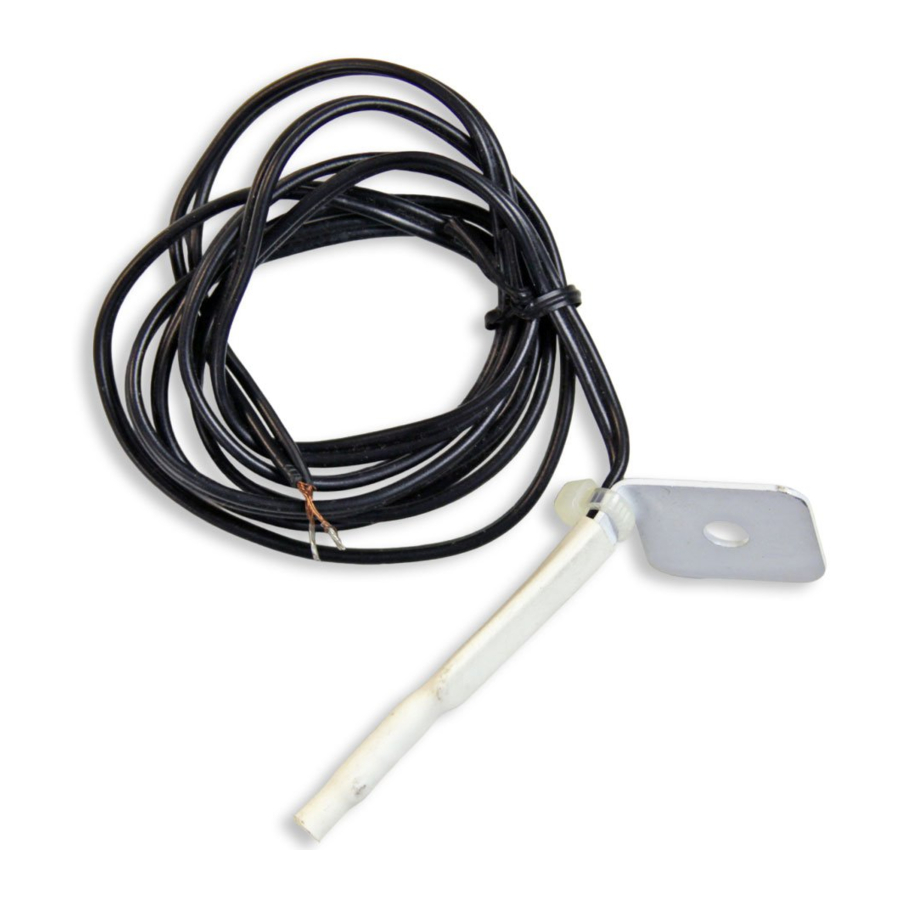
The Aprilaire® Model 8052 temperature sensor can be used with Aprilaire thermostats, support modules, zone controls and the Home Comfort Control™.
INTALLATION INSTRUCTIONS
STEP 1 – INSTALL SENSOR BASED ON THE APPLICATION
Return Air Temperature
- Locate the Aprilaire Model 8052 sensor in the return at least 6" upstream from the fresh air intake so the fresh air does not influence the sensor reading (see fIgure 2).
- Drill a 3/8" hole in the duct and mount the sensor with the supplied screw and mounting bracket (see fIgure 1).


Leaving Air Temperature
- Locate the Aprilaire Model 8052 sensor in the supply trunk, after the heat exchanger and cooling coils (see shaded area in fIgure 2).

- Shield or mount away from direct radiation sources such as sunlight, UV lights, heat exchangers or cooling coils.
- Drill a 3/8" hole in the duct and mount the sensor with the supplied screw and mounting bracket (see fIgure 1).

Outdoor Temperature
- Locate the Aprilaire Model 8052 sensor on the side of the building out of direct sunlight (see fIgure 3).

- Place above the snow line.
- Place at least 3' away from exhaust vents and condensing lines.
- Do not install inside outdoor condensing unit.

Remote Radiant Heat
- Locate the Aprilaire Model 8052 sensor in a radiant floor system.
STEP 2 – DISCONNECT POWER TO THE APRILAIRE CONTROL TO WHICH THE SENSOR WILL BE WIRED

Damage to components can occur if power is not disconnected.
STEP 3 - VERIFY THE SENSOR RESISTANCE
Use an ohm-meter or multimeter to measure the resistance of the sensor. Measure at the wires near the Aprilaire control to check any wire splices. Confirm the resistance corresponds (within 5%) to the temperature where the sensor is installed.
| Temperature (°F) | Resistance (k ) ) |
| 30 | 34.6 |
| 40 | 26.1 |
| 50 | 19.9 |
| 60 | 15.3 |
| 70 | 11.9 |
| 80 | 9.4 |
| 90 | 7.4 |
| 100 | 5.9 |
Note: This measurement should be done without the sensor connected to the Aprilaire control.
STEP 4 – WIRE THE SENSOR TO THE APRILAIRE CONTROL
- Use 18–22 awg wire (2-wire thermostat cable).
- Use the two small wire nuts provided.
- Use less than 300' of wire.
- Do not route wire along 120VAC lines.
Excessive bare wire can lead to shorts. Strip only as much insulation as is necessary.
- The sensor is not polarity specific. Either sensor lead may be connected to either terminal on the Aprilaire control to which it is wired.
- For support modules, use T1 and T2 or T3 and T4 terminals.
- For thermostats, use S1 and S2 (Outdoor) or T1 and T2 (Remote) terminals.
- For zone controls, use DAT, Plenum Sensor or ODT terminals.
- For Home Comfort Control, use RAT, LAT or ODT terminals.
- Use care when routing and stripping the wire. Sharp bends (kinks) or cuts in the wire (particularly susceptible where the insulation has been stripped) can lead to eventual conductor failure.
STEP 5 – RECONNECT POWER TO THE APRILAIRE CONTROL
Sensor Specifications
Resistance @ 77°F (25°C): 10 k![]()
Tolerance @ 77°F (25°C): ±3%
Documents / ResourcesDownload manual
Here you can download full pdf version of manual, it may contain additional safety instructions, warranty information, FCC rules, etc.
Download Aprilaire 8052 - Temperature Sensor Installation Instructions
Advertisement


Need help?
Do you have a question about the 8052 and is the answer not in the manual?
Questions and answers