Table of Contents
Advertisement
Quick Links
Advertisement
Table of Contents

Subscribe to Our Youtube Channel
Related Manuals for Triacta GATEWAY-S


Summary of Contents for Triacta GATEWAY-S
- Page 1 TRIACTA GATEWAY-S ™ Modular 12 Element Meter Installation Guide - DRAFT...
- Page 2 Please note Electrical equipment should be installed, operated, serviced, and maintained only by qualified personnel. No responsibility is assumed by TRIACTA for any consequences arising out of the use of this material. A qualified person is one who has skills and knowledge related to the construction, installation, and operation of electrical equipment and has received safety training to recognize and avoid the hazards involved.
- Page 3 Une distance de séparation d'au moins 20 cm doivent être maintenue entre l'antenne de cet appareil et toutes les personnes. Lanceurs ou ne peuvent pas coexister cette antenne ou capteurs avec d’autres. © 2023 TRIACTA Power Solutions LP All Rights Reserved...
- Page 4 CSA C22.2 No. 61010-1-12. Product Compliance Label The regulatory product label covers all the different types of measurement modules used on this product. Refer to ‘Appendix 2: TRIACTA GATEWAY-S Part Number Configuration Guide’ © 2023 TRIACTA Power Solutions LP All Rights Reserved...
-
Page 5: Table Of Contents
Install CT / Pulse Termination Module into the Meter Base Unit ................20 Install Disconnect Devices for Sense and Control Voltages ..................20 Connect Voltage Wiring .............................. 20 Voltage Module Wiring for Trial GATEWAY-S Meters ....................21 Install and Connect CTs ............................... 25 Connect Pulse Inputs ..............................28 Connect the Ethernet Cable ............................ - Page 6 CT Phasing ................................... 34 CT Shorting and Termination ............................34 CT Naming Designations ............................. 35 Appendix 2: TRIACTA GATEWAY-S Part Number Configuration Guide ................36 Appendix 3: GATEWAY-S Trial Voltage Module Wiring ....................37 Equipment Servicing and Access ............................. 39...
-
Page 7: Introduction
THIS IS A DRAFT VERSION OF THIS DOCUMENT INTENDED FOR FIELD TRIAL USE OF THIS PRODUCT Scope This Guide is for the mechanical and electrical installation of the TRIACTA GATEWAY-S. ™ Refer to the TRIACTA GATEWAY Flex Configuration Tool Guide for instructions on how to configure the TRIACTA GATEWAY-S. -
Page 8: Safety Precautions
NEVER short the secondary of a Potential Transformer (PT). • Always short the secondary of a current transformer prior to disconnecting current input loads. Failure to follow these instructions may result in death or serious injury. © 2023 TRIACTA Power Solutions LP All Rights Reserved... -
Page 9: System Specifications
TRIACTA GATEWAY-S™ System Specifications Table 1 lists the system specifications of the TRIACTA GATEWAY-S Table 1: TRIACTA GATEWAY-S Specification MECHANICAL Dimensions Height: 15.54 in (39.5 cm) Width: 10.25 in (26.0 cm) Depth: 3.86 in (9.8 cm) Weight 8.5 lbs. (3.85 kg) - Fully configured... - Page 10 If the equipment is installed or used in a manner other than that specified in this document, it may void your warranty or impair the protection of the equipment. © 2023 TRIACTA Power Solutions LP All Rights Reserved...
-
Page 11: Dimensions
TRIACTA GATEWAY-S™ Dimensions Figure 1: TRIACTA GATEWAY-S Dimensions © 2023 TRIACTA Power Solutions LP All Rights Reserved... -
Page 12: System Description
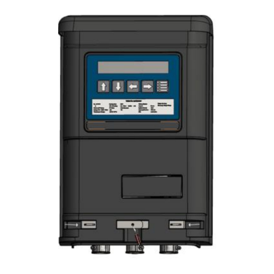
TRIACTA GATEWAY-S Meter Head. The TRIACTA GATEWAY-S Meter Head may be installed at a later time by a technician with no electrical accreditation. Figures 2 and 3 show the external and internal views of the TRIACTA GATEWAY-S meter. -
Page 13: Triacta Gateway-S Meter Base
CT/Pulse Wiring Earth Modules Stud TRIACTA GATEWAY-S Meter Base The TRIACTA GATEWAY-S Meter Base supports connection points for the following: • One Reference/Supply Voltage Input. • One self-shorting input module supports 12 wire pairs for CTs or pulse output devices. -
Page 14: Triacta Gateway-S Measurement Modules
A Pulse Counter Measurement module supports up to 12 pulse counters. TRIACTA GATEWAY-S Voltage Module The Voltage Module of the TRIACTA GATEWAY-S has a single 4-pin terminal block input for both the sense voltage and the control voltage. The voltage inputs on the voltage module (A, B, C and N) provide the sense phase voltages (VAC) used for metering different service types The sense voltage inputs will accept panel voltages from 120VAC to 600VAC. - Page 15 Lug E52164 ZMVV wire connector soldering lug. Torque 486 A-B UL standard for torque NEC. M4 (No. 6-32 2 Newton meters 14 - 18AWG solid or stranded) Must wire according to breaker size © 2023 TRIACTA Power Solutions LP All Rights Reserved...
-
Page 16: Triacta Gateway-S Ct / Termination Modules
TRIACTA GATEWAY-S CT / Termination Modules Current transformers and pulse output devices are connected to the TRIACTA GATEWAY-S via specially designed self-shorting CT / Termination Modules as shown in figure 6. The self-shorting mechanism on each CT / Termination Module is activated when the Wiring Module is not connected to the TRIACTA GATEWAY-S Meter Head unit. -
Page 17: Triacta Gateway-S Flex Configurations
Figure 6: CT / Termination Modules TRIACTA GATEWAY-S FLEX configurations In Flex configuration, The CT inputs in the TRIACTA GATEWAY-S can be each assigned to any combination of 1-element, 2-element or 3-element meters in any order. Each individual CT input pair can be grouped with any other one or two CT pairs to create a 2-Element or 3- element meter. -
Page 18: Pre-Installation Instructions
(OR) Determine the number of pulse counters required Determine the number of TRIACTA GATEWAY-S or TRIACTA GATEWAY-S systems to be installed and ensure adequate space. For clearances, see Figure 7. Determine the type of Measurement Modules required for each TRIACTA GATEWAY-S system. -
Page 19: Installation Instructions
Remove the front cover from the meter by removing the three screws with a #2 Phillips screwdriver. Retain the cover and screws for later re-installation. Mount the TRIACTA GATEWAY-S on the wall and secure it by inserting a screw in each mounting keyhole and tightening the screws. -
Page 20: Install Ct / Pulse Termination Module Into The Meter Base Unit
Install CT / Pulse Termination Module into the Meter Base Unit If a CT / Pulse Screw Terminal Module are ordered with the GATEWAY-S it is shipped pre- installed in the Meter Base module. If a CT/Pulse Whip Cable Module is ordered, it will be shipped separate from the base unit and must be installed as shown in Figure 8 below. -
Page 21: Voltage Module Wiring For Trial Gateway-S Meters
4. If more than one meter is being installed, repeat this procedure for each additional meter. NOTE: The phase wiring sequence A, B, C, and Neutral between the TRIACTA GATEWAY-S meter and the circuit breaker panel must match or the measurement readings will be incorrect. - Page 22 TRIACTA GATEWAY-S™ The Voltage module on the trial GATEWAY-S meters have 6 terminals, i.e. three phases with their respective neutral terminals: Phase A, A ret, Phase B, B ret, Phase C and C ret. The wiring diagram for the aforementioned version of the voltage module can be found in appendix: 3 on Page 37 and 38.
- Page 23 Gateway- S Voltage Module Voltage Module 208 V – 600 V 208 V – 600 V A B C N A B C N Gateway Gateway CT Wiring CT Wiring Module Module © 2023 TRIACTA Power Solutions LP All Rights Reserved...
- Page 24 Gateway- S Voltage Module Voltage Module 208 V – 600 V 208 V – 600 V A B C N A B C N Gateway Gateway CT Wiring CT Wiring Module Module © 2023 TRIACTA Power Solutions LP All Rights Reserved...
-
Page 25: Install And Connect Cts
• Always use a properly rated voltage sensing device to confirm the power is off. • NEVER open circuit a CT; Connecting CTs to a TRIACTA GATEWAY-S CT / Termination Module will ensure that the CT wire pairs are always either shorted or terminated by the Meter Head. - Page 26 When connecting CTs to a CT / Pulse Whip Cable Module, If using a CT / Pulse Screw Terminal Module, skip to step 4. Feed the whip cable through one of the GATEWAY-S conduit adapter plates and conduit connector as shown in Figure 8.
- Page 27 TRIACTA GATEWAY-S™ When installing 5 Amp output CTs Where 5A output CTs are required, they can be connected to a TRIACTA GATEWAY- S with an 80mA CT Measurement Module using TRIACTA 5A:80mA CT converters (Refer to Figure 19.). Install or use an existing sealable metal enclosure outside of the electrical panel within 10 feet of the 5A CTs.
-
Page 28: Connect Pulse Inputs
Each pulse input is compatible with both dry (reed) and solid-state Form A contacts. When the pulsing device provides solid-state form A outputs, the negative terminal from the source device must be connected to the negative (-) terminal of the TRIACTA GATEWAY-S pulse in the terminal block. -
Page 29: Install The Cover
A copy of Figure 17, which is organized to resemble a breaker panel, is provided with each TRIACTA GATEWAY- S and is to be completed and delivered to your system administrator. - Page 30 TRIACTA GATEWAY-S™ Figure 17: Installation Record (sample shown) © 2023 TRIACTA Power Solutions LP All Rights Reserved...
-
Page 31: Maintenance
Meter Head Servicing or Replacement Before removing the Meter Head, be sure to turn off all the power feed/s to the TRIACTA GATEWAY-S Meter Base unit. Always use a properly rated voltage sensing device to confirm power is off. -
Page 32: Appendix 1: Current Transformers Overview
0.333 V 330 ft. (100 m) / 22 AWG As shown in Table 5, 5 Amp secondary CTs can work with the TRIACTA GATEWAY-S by using TRIACTA 5A:100mA or 5A:80mA CT convertors (Figure 19). One convertor is required for each 5A secondary CT. -
Page 33: Ct Orientation
The X1/X2 outputs from each CT for each circuit must be connected to the X1/X2 inputs of each corresponding CT input connection on the appropriate TRIACTA GATEWAY-S CT wiring module. When installing CTs in a panel, ensure that all CT wiring is labeled with the proper X1/X2 designations, or that it follows a standard X1/X2 color pair mapping. -
Page 34: Ct Phasing
CT. The CT / Termination Modules have built-in shorting that is activated whenever the TRIACTA GATEWAY-S Meter Head unit is not installed. 5A CTs should have their own shorting/shunt connector that allows each set of 5A CTs to be independently shorted at the 5A secondary (see Figure 19). -
Page 35: Ct Naming Designations
(named) by a meter number and an element number (meter- element). The TRIACTA GATEWAY-S can support any combination of a single element, two-element, and/or three-element meters in any order, up to a total of 12, elements depending on the number of installed CT modules. -
Page 36: Appendix 2: Triacta Gateway-S Part Number Configuration Guide
TRIACTA GATEWAY-S™ Appendix 2: TRIACTA GATEWAY-S Part Number Configuration Guide G m – 6 x – y 0 6 100mA CT Flex Measurement 333mV CT Flex Module Type Pulse Counter (5 Available, 12 80mA CT flex inputs each) 80mA CT Residential 9... -
Page 37: Appendix 3: Gateway-S Trial Voltage Module Wiring
3 phase – 4 wire Panel 120/208V, 230/400V, 240/416V, 277/480V or 347/600V 120/208V, 230/400V, 240/416V, 277/480V or 347/600V Gateway Gateway CT Wiring CT Wiring Module Module Voltage Module 120V-600 VAC Voltage Module 120V-600 VAC © 2023 TRIACTA Power Solutions LP All Rights Reserved... - Page 38 3 phase – 3 wire Delta Panel 120/208V, 230/400V, 240/416V, 277/480V or 347/600V 230V, 240V, 480V or 600V Delta Gateway CT Wiring Module Gateway Voltage Module CT Wiring 120V-600 VAC Module Voltage Module 120V-600V © 2023 TRIACTA Power Solutions LP All Rights Reserved...
-
Page 39: Equipment Servicing And Access
Component Servicing Individual components are not user-serviceable, and must be returned to TRIACTA Power Solutions for repair. If an equipment fault occurs, do not attempt to repair the faulty component. All maintenance activities should be performed by qualified personnel only. Do not perform any operating or maintenance procedures that are not described in the product documentation. - Page 40 .com TRIACTA Power Solutions LP | TRIACTA.com | info@TRIACTA.com | 613.256.2868 GATEWAY-S Installation Guide © 2022 TRIACTA Power Solutions LP. PowerHawk and TRIACTA GATEWAY are registered trademarks of Metergy Solutions Inc., used under Document # (01/2022) 930-151-01-A.00...
Need help?
Do you have a question about the GATEWAY-S and is the answer not in the manual?
Questions and answers