Download Print this page
Panasonic RF-562DGU Service Manual

Panasonic RF-562DGU Service Manual

Fm-am portable radio

Advertisement

Quick Links

Order No. MD0401005C3
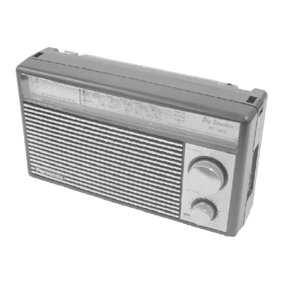
FM-AM PORTABLE RADIO
RF-562DGU / RF-562DGC
Colour
(K) ... Black
SPECIFICATIONS
Specification
RADIO
Frequency Range
FM
88-108 MHz
MW
530-1605 kHz
SW
4.75-18 MHz
Battery; 3 V, two UM-1 (R20/LR20)
Power Requirement
batteries
Speaker
8 cm
800 mW (RMS max)
Power output
Jack
Output
Earphone
Dimensions (W x H x
210 x 120 x 65 mm
D)
Weight
650 g (without batteries)
Notes:
1. Design and specifications are subject to change without notice.
2004 Panasonic AVC Networks Singapore Pte. Ltd. All rights
1

Advertisement

loading

Summary of Contents for Panasonic RF-562DGU

  • Page 1 Power output Jack Output Earphone Dimensions (W x H x 210 x 120 x 65 mm Weight 650 g (without batteries) Notes: 1. Design and specifications are subject to change without notice. 2004 Panasonic AVC Networks Singapore Pte. Ltd. All rights...
  • Page 2: Disassembly And Main Component Replacement Procedures And Operational Check

    reserved. Unauthorized copying and distribution is a violation of law. 1. Operating Instructions 1.1. Location of control 1. Speaker 2. Telescopic antenna FM : Pull out the telescopic antenna and adjust its length and angle for optimum reception. MW : The sensitive ferrite core antenna inside the unit will provide excellent MW reception in most areas.
  • Page 3 1. This section describes procedures for checking the operation of the major printed circuit boards and replacing the main components. 2. For reassembly after operation checks or replacement, reverse the respective procedures. / Special reassembly procedures are described only when required. 3.
  • Page 4: Notes Of Schematic Diagram

    Step 4 : Remove the Volume Knob. Step 5 : Remove all the screws. 3. Notes of Schematic Diagram (All schematic diagrams may be modified at any time with the development of the new technology) Note: : BAND switch : Variable Resistor - The voltage value and waveforms are the reference voltage of this unit measured by DC electronic voltmeter (high impedance) and oscilloscope on the basis of chassis.
  • Page 5 Components identified by mark have special characteristics important for safety. Furthermore, special parts which have purposes of fire-retardant (resistors), high-quality sound (capacitors), low-noise (resistors), etc. are used. When replacing any of components, be sure to use only manufacturer's specified parts shown in the parts list. Caution ! IC, LSI and VLSI are sensitive to static electricity.
  • Page 6 READ CAREFULLY BEFORE ATTEMPTING ALIGNMENT 1. Set volume control to maximum. 2. Set band switch to MW, SW, AM and FM. 3. Set function selector to radio. 4. Set fine tunning to centre. 5. Set power source voltage to 6V DC. 6.
  • Page 7 Signal Generator or Sweep Generator Radio Dial Indicator (Electronic Adjustment Remarks Setting Voltmeter or (Shown in Connections Frequency Oscilloscope) Fig.1) 4.7 MHz Output meter across L9 (SW OSC Fashion a loop of Tuning Adjust for voice coil. MIN) several turns of wire capacitor maximum and radiate a signal...
  • Page 8 Signal Generator or Sweep Radio Dial Setting Indicator (Electronic Adjustment Remarks Generator Voltmeter or (Shown in Oscilloscope) Fig.1) Connections Frequency T1 (FM-IF) [V] High side thru. 10.7 MHz Point of non- Connect vert. amp. of Adjust for 0.001Micro Farad to (SWP) interference.
  • Page 9 DIAL THREADING 1. Remove chasis from cabinet (Refer to 2. Disassembly and Main Component Replacement Procedures and Operational Check) 2. Turn dial drum to fully counter-clockwise. (Turn dial gear to fulley clockwise.). 3. Route dial cord in ordered character (1-6), turn 3 times at Tuning Shaft.
  • Page 10 - The parenthesized indications in the Remarks columns specify the areas or colour. (Refer to the cover page for area or colour) Parts without these indications can be used for all areas. - Capacitor values are in microfarads ( F) unless specified otherwise, P= Pico-farads (pF), F= Farads.
  • Page 11 9.1.2. Cabinet Parts List Ref. No. Part No. Part Name & Description Remarks CABINET AND CHASSIS RFKGF562DGCK FRONT CABINET ASS’Y [M]GC1 RFKGF562DGUK FRONT CABINET ASS’Y [M]GU1 RAS8P26-G SPEAKER RKF4N010ZA-2 BACK CABINET RJT4N010ZA ANT TERMINAL RJC91001 BATT SPRING RKK4N010ZA BATT COVER XEARK132GC ROD ANTENNA RNW823-A...
  • Page 12: Component Part List

    9.2. Component Part list Ref. No. Part No. Part Name & Description Remarks P.C.B RUP4N044XB-2 Main P.C.B. (GC) / Battery P.C.B. (GC) [M] RUP4N044XA-7 Main P.C.B. (GU) / Battery P.C.B. (GU) [M] INTEGRATED CIRCUITS TA7358P IC (FRONT END) AN7236 TRANSISTORS 2SC829BTA TRANSISTOR Q101...
  • Page 13 Ref. No. Part No. Part Name & Description Remarks RLI4B153 FM IFT RLI2B153 AM IFT RLI4B153 FM IFT RLT3F30-1V I.P.T RLT2F41-1V O.P.T CERAMIC FILTERS RVFSFZ455JL CERAMIC FILTER RESISTORS ERDS2TJ220T RESISTOR ERDS2TJ470T RESISTOR ERDS2TJ334T RESISTOR ERDS2TJ331T RESISTOR ERDS2TJ560T RESISTOR ERDS2TJ101T RESISTOR ERDS2TJ103T RESISTOR ERDS2TJ222T...
  • Page 14: Packing Materials & Accessories Parts List

    Ref. No. Part No. Part Name & Description Remarks ECBT0J223NS5 0.022 6.3V ECBT1H151KB5 150 50V ECBT0J223NS5 0.022 6.3V ECBT0J223NS5 0.022 6.3V RCEA1HKA0R1B 0.1 50V ECBT0J223MS5 0.022 6.3V ECBT1C103MS5 0.01 16V ECBT1H470J5 47 50V ECBT1H100JC5 100 50V ECBT1H102KB5 1000P 50V ECBT1H102KB5 1000P 50V ECBT1H102KB5 1000P 50V ECBT1C103NS5 0.01 16V RCEA0JKA101B 100 6.3V...
  • Page 15 FLE0401/K/S/N/E/J...
  • Page 16 MAIN P.C.B. ( RUP4N044XB-2...GC) (RUP4N044XA-7...GU) TP12 J 33 Q101 Q102 R107 R106 C102 Q103 C106 C108 R109 Q104 BATTERY P.C.B. ( RUP4N044XB-2...GC) (RUP4N044XA-7...GU) TP10 TP11 3V (UM-1, R20/L20 BATTERIES)
  • Page 17 SCHEMATIC DIAGRAM -1 : FM SIGNAL LINE MAIN CIRCUIT : +B SIGNAL LINE : MAIN SIGNAL LINE WHIP ANTENNA TA7358P RF AMP FM FRONT END MIXER 2SC829BTA FM IF AMP RLQY30S1W RVF107WDZT 330K RLI4B153 0.01 4.7P S1-1 PRINTED COIL 0.01 4.7P RLQY75S5 0.001...
  • Page 18 MAIN P.C.B. SPEAKER 8cm 800mW (RMS max) 6V (UM-1, R20/L20 BATTERIES) BATTERY P.C.B.
  • Page 19 TA7358P AN7236 2SC829BTA KTC3199LGRAT MA27B1TA KTC3203YAT Cathode Anode...

This manual is also suitable for:

Rf-562dgc