
Related Manuals for Swiss Rotors SR-FS-P-190-0.1


Summary of Contents for Swiss Rotors SR-FS-P-190-0.1
- Page 1 190-560 SR-FS-P/A F PERATING ANUAL 190-560 mm SR-FS-P/A Fan Sets / Operating Manual Ver. 2023-08-01 EN Page 1 of 17...
-
Page 2: Table Of Contents
LIST OF CONTENTS Introduction ....................................3 Product Description ................................. 3 Installation – motor connections ............................8 3.4.1 Analog input ................................11 3.4.2 Modbus RTU ................................. 12 3.4.3 Modbus Parameters ............................. 13 3.5.1 Thermal protection ............................... 15 3.5.2 Under and over voltage ............................15 3.5.3 Blocked rotor protection ............................ -
Page 3: Introduction
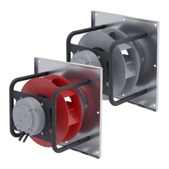
1 INTRODUCTION LEGAL DISCLAIMER This Operations Manual (OM) applies to products of Swiss Rotors. This document is a property of Swiss Rotors, licensors or affiliates, protected by international trademark and copyright laws. Due to continuous product improvement, Swiss Rotors reserves the right to make changes to its content without prior notice. - Page 4 All parts create perfectly optimized air supply/exhaust device. Depending on customer needs, FanSet’s comes in few configurations ( Figure 1 - Appearance of the SR-FS-P-190-0.1 Fan Set Figure 2 - Appearance of the SR-FS-P/A-225-0.3 → SR-FS-P/A-400-2.5 Fan Sets Figure 3 - Appearance of the SR-FS-A-315-560 Fan Sets Table 1 - Dimmensions of SR-FS-P/A-225-0.3...
- Page 5 SR-FS-A-315-0.3 268 mm 246 mm 358 mm 15 mm 450 mm 411 mm 328 mm 9 mm SR-FS-P-225-0.7 250 mm 210 mm 254 mm 15 mm 315 mm 288 mm 228 mm 9 mm SR-FS-A-225-0.7 248 mm 210 mm 254 mm 15 mm 315 mm 288 mm...
- Page 6 Figure 5 - Recommended clearance at inlet and outlet side PRODUCT IDENTIFICATION SYSTEM Each fan is equipped with original name plate where exact model is marked (dot in field corresponding to actual model). The syntax of the code used to designate individual fan models is presented in Table 3. Table 3 - Product code syntax Code Code sector meaning...
- Page 7 ∆�� − ������������ ������������������������ ���������������� [����] Value of K-factor (�� ) for Swiss Rotors Fan Set’s range is shown on below attached Table 4. K-factors were determined during testing under standard conditions. Table 4 - factor values of Fan Set depending on the Impeller size and motor power...
-
Page 8: Installation - Motor Connections
PRODUCT DESCRIPTION Swiss Rotors Fans are equipped with various motor configurations tailored to the needs and electrical requirements of our customers. To get the right parameters and to ensure proper operation characteristics of the fans, range of motors includes a few basic configurations available. - Page 9 -25°C to 40°C IP 54 Note: Given setups are explanatory. Swiss Rotors reserves the right to change those configurations without informing. Any modification or configuration changes other than proposed should be reported and consulted in details with Swiss Rotors technical department first.
- Page 10 *Depending on the type of meter used to measure RMS or TRMS current, there may be a difference in the current indication. CONNECTION AND DIAGRAMS To perform the correct setup, please refer to the following diagrams representing possible ways of motor connection.
-
Page 11: Analog Input
Figure 10: Left: Motor EC092 series and EC102 series; Right: EC092 series and EC102 series CONNECTION DIAGRAM Figure 11 -Left: EC137 Series CONNECTION DIAGRAM; Right: Wires and factory connectors for EC137,180 Series. COMMUNICATION The motors can be controlled via an analog connection and using the Modbus protocol. The EC169W-B190 / 44P1-05 engine can only be controlled using the Modbus protocol. -
Page 12: Modbus Rtu
Figure 12 - RPM/voltage charts with analogue connection. In case of controlling more motors, it is necessary to provide the appropriate current for the analog output. As it is shown in the Table 7 Table 7 - Table of current according to number of controlled motors Number of motors U [V] R [kΩ]... -
Page 13: Modbus Parameters
To connect PC and drive over serial line (MODBUS) RS-23/USB to RS-485, use of converter is needed. Table 8 - ModBUS Default configuration and supported commands DEFAULT CONFIGURATION SUPPORTED ModBUS COMMANDS ModBUS address 1 for Fan 0x01: Read Coils Baud Rate 9600 0x02: Read Input START bit 0x03: Read Holding Registers... - Page 14 Table 12 - Description of Modbus Holding Registers Resol Address Function Range Description Level ution Set point 0..10000 Performance set point for speed depends on operation mode. 0,01% Direction 0..65535 Motor direction: 0: clockwise rotation. >0: anti-clockwise rotation MinRPM.. Max rpm allowed in normal operation. External control will use Maximum Speed MaxRPM[level+1] this as set point maximum.
-
Page 15: Thermal Protection
4 MAINTENANCE GENERAL INSPECTION CHECK-LIST Swiss Rotors strongly recommends checking the condition of fans systematically. Technical control is obliged to the user. Properly frequent checks allow early detection of irregularities in the system and may help avoiding serious damages resulting from various random factors. Please refer to our general proposed inspection checklist (Table 14). -
Page 16: Transportation
GUIDELINES FOR AVOIDING INCORRECT OPERATION Following list includes an unwanted, and improper usage of Swiss Rotors fan units. Such behavior may damage the product as well as other parts of equipment inside the AHU system. There is also a high risk that improper operation may harm the user causing serious injuries. -
Page 17: Examine The Package
2. Pay attention to the way in which the goods were delivered. 3. Swiss Rotors prepares shipments using professional labels and transport descriptions. If you see that the shipping company did not follow the instructions given on the labels - refuse to accept the parcel.
Need help?
Do you have a question about the SR-FS-P-190-0.1 and is the answer not in the manual?
Questions and answers