
Related Manuals for Swiss Rotors SR P-HE


Summary of Contents for Swiss Rotors SR P-HE
- Page 1 FanSet FANSET SR P/A-HE CENTRIFUGAL FANS OPERATION AND MAINTENANCE MANUAL FOR IMPELELRS: 190-315 Version 1.0.1 www.swissrotors.com...
-
Page 2: Table Of Contents
Please read the following documentation carefully before installation of our product. In case of doubts contact Swiss Rotors official support. 1. TABLE OF CONTENT INTRODUCTION..........................2 Preface............................3 Disclaimer............................3 PRODUCT DESCRIPTION.......................4 Construction...........................4 Principle of operation........................6 Operational limits...........................7 Air Volume measuring........................7 INSTALLATION – MOTOR CONNECTION..................9 General safety..........................9... -
Page 3: Preface
The following instruction, unless otherwise stated, applies to all Swiss Rotors FanSet units. In exceptional circumstances, differences will be noted. This document is a property of Swiss Rotors, licensors or affiliates, protected by international trademark and copyright laws. Swiss Rotors constantly develops its products and this document is subject to change without notice. -
Page 4: Product Description
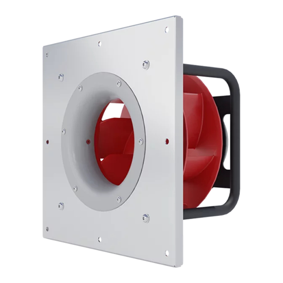
PRODUCT DESCRIPTION Construction Swiss Rotors new high efficiency FanSet range is designed especially to replace an old fan systems solutions that makes air handling units low efficient. FanSet consists of front steel plate with inlet cone that is integrated with specific motor tubular support. Properly selected EC electric motor mounted on the tubular support is driving a radial impeller located directly on the motor flange. - Page 5 Figure 1. FanSet SR190 Series (bottom) and FanSet SR225, SR250, SR315 Series (top) Figure 2. Swiss Rotors FanSet overall dimensions, see Tab. 1 Version 1.0.1...
-
Page 6: Principle Of Operation
Principle of operation FanSet is a device used to supply and exhaust air. The engine, mounted in the housing, drives the impeller located inside. The fan, after accelerating to the dedicated rotational speed, is able to force the flow through the air handling unit. Special designed 7 backward-curved blades in frame redirect exhaust of air at 90 degrees so that the centrifugal effect increases the pressure and power of the fan. -
Page 7: Operational Limits
Operational limits Impeller units inside the FanSet are prepared to work within temperature conditions oscillating between -25oC and +50oC. All FanSet’s are tested for flammability according to UL-94. Each device is adapted to work vertically and horizontally. The label consists of the following Fan Set Manufactured in Poland information:... - Page 8 K factor can be converted to the correspondent k’ using below formula: Value of K-factor (k_10) for Swiss Rotors FanSet’s range is shown on below attached table Fan Set Type Motor power...
-
Page 9: Installation - Motor Connection
NOTE: It is the user and the installer responsibility to provide the system with the proper grounding and protection in accordance with national and local standards. Swiss Rotors is not responsible for any damages or injuries caused by incorrect installation, bad circuits or other failures. -
Page 10: Technical Specifications
RATED RATED RATED SPEED OPERATING MOTOR TYPE FAN TYPE FREQUENCY OUTPUT VOLTAGE SPEED CONTROL TEMP. [C0] POWER SR190 EC169W- 230V AC 50/60Hz 128W 4490 0~10VDC, Modbus to 50 -B190/44P1-05 SR-P-HE-225-03 EC092/25E3G05-03 230V AC 50/60Hz 349W 3600 0~10VDC, Modbus to 50 SR-A-HE-225-03 EC092/25E3G05-03 230V AC... -
Page 11: Connection & Diagrams
Connection & Diagrams To perform the correct setup, please refer to the following diagrams representing possible ways of motor connection. Installation and connection can be done by qualified personnel only. Failure in performing in any of this operations may result in risk of fatal injury, electric shock, incorrect mounting or product damage. - Page 12 Figure 8. EC169W-B190/44P1-05 CONNECTION DIAGRAM Figure 9. Wires and factory connectors EC169W-B190/44P1-05 Version 1.0.1...
- Page 13 Motor EC092 series and EC102 series Figure 14. EC092 series and EC102 series CONNECTION DIAGRAM Version 1.0.1...
- Page 14 Figure 11. EC137 Series CONNECTION DIAGRAM. Figure 12. Wires and factory connectors for EC137 Series. Version 1.0.1...
-
Page 15: Communication
Communication The motors can be controlled via an analog connection and using the Modbus protocol. The EC169W-B190 / 44P1-05 engine can only be controlled using the Modbus protocol. The 092 and 102 series motors can be controlled in both ways. The parameters and control methods are presented below. -
Page 16: Modbus Parameters
Drives uses the two-wire system where the communication between master and slave is half duplex, i.e. it cannot transmit and receive at the same time. Each signal uses one twisted pair line — two wires twisted around themselves. The signal on one wire is ideally the exact opposite of the signal on the second wire. - Page 17 Coils Address Function Range Description Motor ON/OFF Indication, 1=ON, 0=OFF Reset Controller 1=Reset controller Discrete status bits Address Function Range Description Level Under Voltage 1=Voltage too low to run Over Voltage 1=Voltage too high to run IGBT Overcurrent 1=Overcurrent protection tripped 1=Temperature protection active, power reduced Phase Loss...
- Page 18 Holding Registers Address Function Range Description LEVEL Resolution Set point 0..10000 Performance set point for speed depends on operation 0, 1 0,01% mode. Direction 0..65535 Motor direction: 0: clockwise rotation. >0: anti-clockwise rotation Maximum Speed MinRPM.. Ma- Max rpm allowed in normal operation. External control 0, 1 xRPM[level+1] will use this as set point maximum.
-
Page 19: Protections
Input Registers Address Function Range Description LEVEL Resolution HW Version Hardware version FW Version Firmware version 2..3 RESERVED Speed 0..32767 Controller -50..150 °C 0.01 temperature DC Bus voltage in V Stator IRMS RMS Stator current in A 0.001 Power Analogue1 -300..2000 Analogue input 1 voltage 0.01V... -
Page 20: Maintenance
MAINTENANCE Maintenance Swiss Rotors strongly recommends checking the condition of fans systematically. Technical control is obliged to the user. Properly frequent checks allow early detection of irregularities in the system and may help avoiding serious damages resulting from various random factors. Please refer to our general proposed inspection checklist presented below. -
Page 21: Guidelines For Avoiding Incorrect Operation
5.2 Guidelines for avoiding incorrect operation Following list includes an unwanted, and improper usage of Swiss Rotors fan units.Such behavior may damage the product as well as other parts of equipment inside theAHU system. There is also a high risk that improper operation may harm the usercausing serious injuries. -
Page 22: Quality Control
Pay attention to the way in which the goods were delivered. Swiss Rotors prepares shipments using professional labels and transport descriptions. If you see that the shipping company did not follow the instructions given on the labels - refuse to accept the parcel.
Need help?
Do you have a question about the SR P-HE and is the answer not in the manual?
Questions and answers