Advertisement
Quick Links
Advertisement

Related Manuals for DAYLIFF HPW150

Summary of Contents for DAYLIFF HPW150
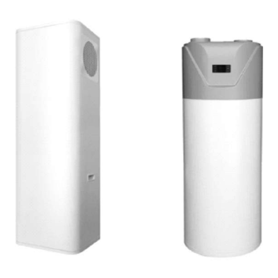
- Page 1 All in One Heat Pump HPW150 HPW200 & 300...
- Page 2 1. SPECIFICATIONS 2. SYMBOLS & WARNINGS 3. EQUIPMENT CONTENTS 4. INSTALLATION 5. OPERATION AND MAINTENANCE 6. TROUBLE SHOOTING 7. TERMS OF WARRANTY © Davis & Shirtliff Ltd 2023 Contents herein are not warranted...
- Page 3 HPW150 HPW200 & 300 Dayliff HPW Heat Pump Hot Water Systems are designed for all domestic water heating applications that utilise the high efficiency benefits of heat pump technology. The integral systems combine a hot water storage tank with an efficient heat pump that generates heat from ambient air by utilising the natural heat generating phenomenon of the gas evaporation/condensation cycle.
- Page 4 TECHNICAL SPECIFICATIONS HPW150 HPW200 HPW300 Model Water Tank Volume, Liters Heating Capacity, kW Rated/Max Input Power, kW 0.6/3 Fan Flow Side Rated/Max Current, A 2.7/15 Inlet/Outlet ¾” Net Dimensions, mm 500x500x1670 620Diax1638 620Diax2038 Net Weight, kgs Hot Air Cold Water...
- Page 5 Any modication and improper repair is not advised as it may cause re, electric shock and injury. WARNING Ensure electrical supply is compatible with the Rated Current value should not be less than 10A and power. WARNING Install the equipment in a cool dry place and that is well ventilated and away from children.
- Page 6 Do not touch fan with your hands or other objects else may result in injury. WARNING Equipment is provided with complete isolation between water and electricity, without electric shock problem, more safety. NOTE 3. INSTALLATION 3.1 Equipment Contents Refrigerant Outlet Refrigerant Inlet Fig 1: Single Coil Layout Ÿ...
- Page 7 Ÿ The unit is provided with automatic start-up and shutdown, automatic defrosting by by way of revising refrigerant cycle to save the extra operation. Ÿ A non return valve must be installed on the cold water inlet. Hot water outlet One-way valve Dryer Magnesiarods...
- Page 8 Air Inlet Barrier Air Outlet >200mm >200mm >200mm Control Panel >200mm Fig 4: Installation Layout Ÿ If heat pump is installed in the basement or indoor or other airtight spaces, ensure there is sufficient air circulation. The air duct total length should be equal or less than 6 meters, and the duct diameter should be equal or more than 150 mm.
- Page 9 Model HPW150 1670 1214 1638 1013 HPW200 2038 1413 HPW300 Fig 6: Connection Dimensions 3.3 Water Pipe Installation Instructions Do not use iron pipe to connect to heat pump, instead use CPVC pipe, PPR pipe or UPVC pipe WARNING Ÿ Water pipes work life should not be less than heat pump’s work life.
- Page 10 Max 2.2" Diameter atleast 50mm larger than heat pump Fig 7: Drainage Layout 3.4 Sitting and Air Duct Installation Instructions Air inlet Air Outlet Air Outlet Air inlet Air Outlet Air inlet (1) Air inlet and outlet with duct (2) Only air outlet with duct (3) Only air inlet with duct A+B <...
- Page 11 Ÿ An air filter should be installed at the inlet to trap air debris Leakage Power Min. Cable diameter Manual Switch Protection Model Supply (mm ) Device Size (continous Ground Capacity Fuse length Wire Below 30mA 220V/50Hz HPW150 <30m) 0.1 sec >2.5 >ø1.0mm >20...
- Page 12 Leakage Power Min. Cable diameter Manual Switch Protection Model Supply (mm2) Device Size (continous Ground Capacity Fuse length Wire Below 30mA HPW200/300 220V/50Hz <30m) 0.1 sec >2.5 >ø1.0mm >20 Directly connect power supply wire with hplug when using the heat pump NOTE Leakage Protection Leakage Protection...
- Page 13 Electric Wiring Diagram HPW150...
- Page 14 PowerIn /~ / 220V 50Hz Coil temp . Ambient temp. 4 way valve Exhaust temp. Capacitor High speed Water tank temp. Low speed Suction temp. Reserved Reserved E-heater COM. Water High flow pressure pressure switch switch switch HPW200/300...
- Page 15 First Time Operation Feeding water: when using the unit for the first time (or reuse it after the tank is empty ), before connecting the unit with power, ensure that the tank is full of water and open both cold water in and hot water out as below Ÿ...
- Page 16 Automatic defrosting. Ÿ Forced defrost. Ÿ The error code display and query Ÿ Key-Lock Function Ÿ Anti-freezing function Ÿ In the absence of a wire controller or if faulty, the system will run automatically. Wire Controller and Operation HPW150 HPW200/300...
- Page 17 Symbol Status Meaning Constantly bright Heat pump is on Extinguished Heat pump is off At cooling mode Constantly bright At heating mode Constantly bright Needs repair Constantly bright On AUTO mode Constantly bright Extinguished Currently in the manual set temperature state This unit is a water connection heat pump Constantly bright Extinguished...
- Page 18 Symbol Status Meaning Start timing water return function Constantly bright Start manual water return function Flashing Turn off water return (timing/manual) function Extinguished Currently the return water is in regular timing working period Display Currently set start time of backwater working time Flashing Currently the return water is in the non-working hours Display...
- Page 19 Button Instruction 1. Under the main interface, press to switch between automatic/manual temperature control mode. “AUTO” is displayed in the automatic mode and is not displayed when manual 2. In the main interface, press and hold for 3 seconds to enter the parameter interface.
- Page 20 4.3 Set the water temperature: • In manual mode, press“∧” or “∨” key to enter the water temperature setting state. Then starts to display the setting symbol and display the corresponding water temperature set according to the current cooling or heating mode. •...
- Page 21 • The three time slots are as follows; 05:00-07:00; 16:00-18:00; and 20:00-00:00. • When the timing control mode is enabled, the corresponding symbols are displayed in the working period (ON) and the non-working period (OFF) respectively. • In the power-on state, heating/cooling is performed only during the programmed period, and the rest of the time , the unit is not heating/cooling.
- Page 22 4.9 Forced sterilization • If the controller is in the normal display state and it is currently in the heating mode, press the “M”+“ ∧”+“ ∨” button at the same time for more than 5 seconds to activate or deactivate the “sterilization” function. •...
- Page 23 Name Code Remark Fluorine cycle/water cycle 0=water cycle; 1=fluorine cycle heat pump High pressure switch 0=disconnect; 1=close Low pressure switch 0=disconnect; 1=close Water ow switch 0=disconnect; 1=close EEV Value Measured value Evaporator coil sensor Measured value Ambient temperature sensor Measured value Absorption temperature Measured value sensor...
- Page 24 Electric heater control: • At heating mode, when the water tank temperature ≤ set temperature -20 °C, electric heater starts, and the symbol lights up. • When the water tank temperature ≥ the set temperature, the electric heater is turned off and the symbol is extinguished.
- Page 25 • During this process, press and hold the “cold and hot” button for 1 second to manually cancel the manual water return function. Timed return water: • When the controller is in the normal display state, press and hold the “ ”...
- Page 26 • At this time, the electric heater is started to heat the water to 75℃ and the water temperature is maintained at 70 to 75℃ for 30 minutes, then the sterilization mode will be automatically exited. • After starting the manual sterilization function, press and hold the “M” + “∧” + “∨” button for 5 seconds or more at the same time to exit the manual sterilization mode.
- Page 27 High exhaust temperature failure: • After the compressor starts running for 1 minute, when the exhaust gas temperature is detected to be higher than or equal to the exhaust high temperature protection value by 110℃ for 10 consecutive seconds, an high exhaust temperature alarm occurs and the compressor stops.
- Page 28 • When the water tank or ambient temperature sensor are faulty, electric heating operation is not allowed. “11E”, “12E”, “13E” ", "14E", "15E", "17E", "18E", "19E". are correspondingly displayed when the coil temperature sensor, ambient temperature sensor, exhaust temperature sensor, inlet water temperature sensor/tank temperature sensor, absorb temperature sensor, and outlet water temperature sensor/return water temperature sensor are faulty.
- Page 29 8. Any air pocket in the water pipe is expelled,and all valves are opened; 9. Leakage protection device works well. 10. Input water pressure is less than 6 bar for HPW200/300 and 4 bar for HPW150. Maintenance Ÿ Frequently check power plug and sockets to make sure both of them have been connected well and reliably, grounded and have no over-heating effect.
- Page 30 T h e t e m p e r a t u r e controller is damaged Contact Dayliff retailer The circuit board of the i n d i c a t o r l a m p i s...
- Page 31 I) General Liability • In lieu of any warranty, condition or liability implied by law, the liability of Dayliff (hereafter called the Distributor) in respect of any defect or failure of equipment supplied is limited to making good by replacement or...
- Page 32 INSXXXA-00/22...
Need help?
Do you have a question about the HPW150 and is the answer not in the manual?
Questions and answers
Is the inner container enamel or stainless steel