Table of Contents
Advertisement
Quick Links
Advertisement
Table of Contents

Related Manuals for DAYLIFF SPS-190

Summary of Contents for DAYLIFF SPS-190
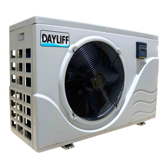
- Page 1 Heat Pumps...
-
Page 3: Table Of Contents
SPECIFICATIONS 2. SYMBOLS & WARNINGS 3. EQUIPMENT CONTENTS 4. INSTALLATION 4.1 Installation Space Requirement 4.2 Installation Base for the Heat Pump 4.3 Installation of the Pipeline 4.4 Installation of Water Pump & Flow Switch 4.5 Installation of Electric Components 4.6 Appearance and Button Functions of Controller 4.7 Protection Specications 5. -
Page 4: Specifications
There are a number of options available, but a particularly effective solution is the Dayliff Heat Pump. Heat Pumps utilise energy from two sources, heat from the ambient air and electrical power to run a compressor in a reverse refrigeration cycle, the compression process extracting heat from the ambient air for transfer to the pool water. -
Page 5: Symbols & Warnings
• Remote controller to set temperature up to 40 C with digital system setting and fault indicators. Dayliff Heat Pumps are robust and efficient units that are the ideal solution for cost effective pool heating in a variety of conditions. - Page 6 WARNING When the unit needs to be removed, re-installed or repaired, contact Dayliff retailer or have a qualied person to do it. If the installation is not well done, it may cause failure, electric WARNING shock, re, leaking, etc.
-
Page 7: Equipment Contents
3. EQUIPMENT CONTENTS Item No. Description Quantity Installation manual Guidance on proper installation To automate control of the heat pump Controller with connecting line To protect heat pump against running Water flow switch under flow condition Certificate of approval Proof of product quality Warranty Card Warranty Certificate Water pump is purchased separately and must be properly... -
Page 8: Installation Base For The Heat Pump
4.2 Installation base for the heat pump Anchor Bolt Anchor Bolt Screw nut/washer Drainage Tray Heat Pump Heat Pump Shock absorb Installation Base Drainage Tray Concrete Fig 3: Firm Installation Base 1. When moving use four or more soft lifting belts to move the equipment. 2. - Page 9 Chemical Flexible Check Sand Feeding Flared Hair Pressure Flow Pump Valve Filter Dosing Connection Valve Filter Gauge Tank Joint Collector Valve Switch System Water Temperature Sensor Swimming Pool Wire Controller Water Pump Power Line Dedicated Pump for Heat Swimming Pool Filter Filter pump units...
-
Page 10: Installation Of Water Pump & Flow Switch
The swimming pool heat pump uses titanium heat ex-changer and may be connected to the swimming pool directly. A water ltration unit must be installed before water goes into the heat WARNING pump, minimum size about 40mic. The non-return valve is recommended for each unit to prevent the water back flow. Ÿ... -
Page 11: Installation Of Electric Components
The flow switch must be installed on a straight pipeline and there must be more than Ÿ five times the length of the pipe diameter at its two sides. The direction of flow must follow the arrow on the switch. The terminal block should be easily accessed for maintenance. - Page 12 Special Requirement 1. For 1pH circulation pump connect live line with one output port of the three phase lines KM2 and connect the pump null line with the null port XT1. 2. The circulation pump must be installed in the water flow pipe line system between the heat pump and the pool outlet line.
-
Page 13: Appearance And Button Functions Of Controller
4.6 Appearance and button functions of controller Defrost Cooling Mode Heating Mode Constant Temp. Mode Water Pump is Running Inlet Water Temp. Outlet Water Temp Keyboard is Locked Timer is Working Fan is running Setting Time/ Power On/Off Timer Query the running parameters Changing the working Setting Water... - Page 14 Water Temperature Setting ▲ ▲ Under the condition of power on, press “ “ or “ “ key to set the water temperature. Heating Mode: water temperature (L3): 20 C~40 C, default: 28 C. Cooling Mode: water temperature (L4): 7 C~20 C, default: 12 C. Constant Temperature Mode: temperature (L1): 7 C~40 C, default: 28 C.
-
Page 15: Protection SpeciCations
Operating Parameters Meaning Code Coil temperature Discharge air temperature Exhaust temperature Ambient temperature lnput water temperature Return water temperature Unused Compressor Current Unused Expansion Valve Fault Codes Meaning Fault Code Default phase Loss of phase Water switch Anti freezing High pressure Low pressure Communication Time limited... - Page 16 High Pressure Protection 1. If the high pressure switch is disconnected less than three times per hour, display panel will show fault code with alarm. 2. The compressor, fan and water pump will stop working and restart again after the high pressure switch is reconnected.
-
Page 17: Operation And Maintenance
5. OPERATION & MAINTENANCE 5.1 Routine Maintenance Control and protect the equipment. Ÿ Pay close attention to whether all the operation parameters are normal during Ÿ system working. Regularly examine whether the electrical connection is loose, if not tighten. Ÿ Regularly examine the reliability of electrical components and change failed or Ÿ... -
Page 18: Routine Maintenance
5.5 Routine Maintenance Conduct regular maintenance to make sure the unit is running in good condition. In the event of a fire turn off the power switch immediately and put out the fire with Ÿ fire extinguisher. To prevent flammable gas from exploding: the unit working environment should Ÿ... -
Page 19: Trouble Shooting
6. TROUBLE SHOOTING Presence of air or other non condensable gases Vent the air from the system in the system Water heat exchanger is Wash and clean the heat exchanger Discharge pressure too scaled or fouled high The circulation water Examine the water system pipeline and volume is not sufficient pump... - Page 20 Adjust overheat temperature, examine Ambient temperature is whether there is flourine leakage from the too low expansion valve The evaporator liquid Clear blocked inlet/ suction pipe Suction pressure is low i n l e t o r c o m p r e s s o r suction pipe is blocked Examine flourine leakage Repair expansion joint...
- Page 21 Examine the voltage and ensure it is within The voltage is too high or the recommended range too low Compressor stopped Discharge pressure is too because of built in Examine the discharge pressure and correct high thermostat Examine whether there is fluorine leakage The refrigerant in the and repair system is not enough...
-
Page 22: Terms Of Warranty
7. TERMS OF WARRANTY I) General Liability • In lieu of any warranty, condition or liability implied by law, the liability of Davis & Shirtliff (hereafter called the Company) in respect of any defect or failure of equipment supplied is limited to making good by replacement or repair (at the Company's discretion) defects which under proper use appear therein and arise solely from faulty design, materials or workmanship within a specified period. - Page 24 INSXXXA-00/22...
Need help?
Do you have a question about the SPS-190 and is the answer not in the manual?
Questions and answers
error 7 in dayliff heat pump
Error 7 in the DAYLIFF SPS-190 heat pump indicates that the compressor cannot start. Possible causes include:
- Control circuit not connected or not functioning
- No current flow
- Pressure too low causing the pressure switch not to conduct
- Contactor coil is burnt
- Refrigerant is low and needs refilling
- Water system failure or relay wiring is tripped
Check the power supply, refrigerant level, wiring, and control system to resolve the issue.
This answer is automatically generated
My pool not heating even though the heater is on
The DAYLIFF SPS-190 pool heater may not be heating the pool due to several potential reasons:
1. Low Water Flow – The system requires proper water flow for heating. Check if the water circulation is adequate.
2. Low Refrigerant Level – If the refrigerant level is too low, the system may not function correctly. Inspect and refill if necessary.
3. Electrical Issues – The compressor may not be starting due to electrical problems such as a tripped relay, burnt contactor coil, or power supply failure. Verify power connections.
4. Incorrect Settings – Ensure the heater is set to the correct mode and temperature range. The heating mode should be active with a temperature setting between 20°C and 40°C.
5. Compressor Protection Activated – The built-in protection system could have triggered due to high/low pressure or electrical overload. Reset and check for any underlying issues.
If the issue persists, further inspection or professional servicing may be required.
This answer is automatically generated