Table of Contents
Advertisement
Quick Links
Advertisement
Table of Contents

Related Manuals for futuredesion L22


Summary of Contents for futuredesion L22
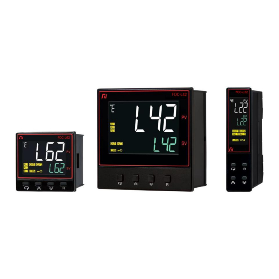
- Page 1 PROCESS LIMIT CONTROLLER L22/L62/L42 USER MANUAL UML0621B April 2023...
- Page 2 FDC is not liable for any damages incurred to equipment and/or personnel during installation or use of the L22, L62 or L42 process limit control as explained in this document. The end user must acquire sufficient knowledge and skill set prior to using the process limit control in the application and follow all the local standards and regulations to meet all applicable safety requirements.
-
Page 3: Table Of Contents
1.3 Specifications ......................6 1.4 Ordering Code ......................9 1.4.1 L42 Ordering Code .......................... 9 1.4.2 L62 Ordering Code ........................10 1.4.3 L22 Ordering Code ........................11 1.4.4 Accessories ........................... 11 1.4.5 Related Products ........................... 11 1.5 Programming Port ....................12 1.6 Keys and Displays .................... - Page 4 L22/L62/L42 Process Limit Control 2.8 Event Input Wiring ....................42 2.9 Retransmission Wiring .................... 42 2.10 RS-485 Serial Communication Wiring ..............43 3 Configuration ......................44 3.1 Security ........................44 3.1.1 Calibration Security ........................45 3.2 Input Settings ......................45 3.2.1 Digital Filter ............................
-
Page 5: Introduction
L22/L62/L42 Process Limit Control 1 Introduction The L22, L62 and L42 are FM Approved process limit controls that can be configured either as a high limit, a low limit or both a high and low limit control. The limit controls can be powered by either an 11-26 or 90-250 VDC / VAC supply, incorporating a 2 ampere (resistive) relay output as standard. -
Page 6: Specifications
L22/L62/L42 Process Limit Control 1.3 Specifications Specification Power Supply 90 to 250VAC, 47 to 63Hz, 20 to 28 VAC,47-63Hz / 11 to 40 VDC Power Consumption 8VA, 4W Maximum 10VA, 5W Maximum., 12VA, 6W Maximum Over Voltage Category Signal Input... - Page 7 L22/L62/L42 Process Limit Control Specification Relay Type Form A Relay Rating 2A, 240VAC, 200000 Life Cycles for Resistive Load 5VDC/30mA, Current Limiting Resistance 66Ω, 14VDC/40mA Sourced Voltage Output 2 / Alarm 1 Limit Control Annunciator Function Type Relay, Source Voltage...
- Page 8 L22/L62/L42 Process Limit Control Specification Altitude 2000 Meters Maximum Pollution Degree II Insulation 20MΩ Minimum (@500V DC) Resistance Dielectric Strength 2000VAC,50/60 Hz for 1 Minute Vibration 10 to 55 Hz, 10m/s for 2 Hours Resistance Shock Resistance 200 m/s (20g)
-
Page 9: Ordering Code
L22/L62/L42 Process Limit Control 1.4 Ordering Code 1.4.1 L42 Ordering Code FDC - L42 - Power Input 90 to 250 VAC, 47-63Hz 20 to 28 VAC, 47-63Hz / 11 to 40 VDC Output 1 Form A Relay (2A, 250V) SSRD, 5VDC/30mA (33Ω, ¼W *2) -
Page 10: L62 Ordering Code
L22/L62/L42 Process Limit Control 1.4.2 L62 Ordering Code FDC - L62 - Power Input 90 to 250 VAC, 47-63Hz 20 to 28 VAC, 47-63Hz / 11 to 40 VDC Output 1 Form A Relay (2A, 250V) SSRD, 5VDC/30mA (33Ω, ¼W *2) -
Page 11: L22 Ordering Code
Special order AA-ZZ 1.4.4 Accessories OM94-7 14VDC/40mA SSR Drive Module OM98-3 Isolated 4-20mA/0-20mA Retransmission Module for L22 OM98-5 Isolated 0-10VDC Retransmission Module for L22 CM98-3 Isolated 4-20mA/0-20mA Retransmission Module for L62 and L42 CM98-5 Isolated 0-10VDC Retransmission Module for L62 and L42... -
Page 12: Programming Port
L22/L62/L42 Process Limit Control 1.5 Programming Port A Micro USB Port provided on the limit control can be used to connect it to a PC by using a programming port cable (CC98-1) and adapter (PA98-1) for firmware updates. Micro USB Programming Port... -
Page 13: Keys And Displays
L22/L62/L42 Process Limit Control 1.6 Keys and Displays The following figures depict the interface arrangement for each of the process limit control models. L62 Front Panel Keys and Display L22 Front Panel Keys and Display... -
Page 14: Keypad Operation
L22/L62/L42 Process Limit Control L42 Front Panel Keys and Display 1.6.1 Keypad Operation SCROLL KEY: This scroll key is used to select a parameter to be viewed and/or adjusted as well as navigate to the next parameter. Repeatedly pressing and releasing the key advances through each available parameter under the current menu. -
Page 15: Display Operation
L22/L62/L42 Process Limit Control Note: If the reset key is left pressed, only one reset operation will occur. If the unit subsequently goes into a state where reset is required again, the reset key (or remote reset contacts) must be released (opened) and pressed (closed) again. -
Page 16: Menu Navigation
L22/L62/L42 Process Limit Control 1.7 Menu Navigation The process limit control provides three menu groups: User Menu: Provides access to the low/high limit set point values, viewing of minimum and maximum process values, time in limit condition and select parameter values as defined in setup. -
Page 17: User Access Menu
L22/L62/L42 Process Limit Control 1.7.1 User Access Menu The user menu is the default (home) menu of the limit control. Repeatedly pressing the scroll key cycles through the list of parameters as shown below. When scrolling through the available parameters, the upper display will provide the parameter description, i.e., HSP1 for high limit set point 1 for example, while the... -
Page 18: Setup Menu
L22/L62/L42 Process Limit Control 1.7.2 Setup Menu The setup menu is divided into six categories to make the configuration process easier. To access the setup menu from the user menu, press and hold the scroll key for ~5 seconds. One the upper display shows SEt (for setup menu), immediately release the scroll key. -
Page 19: Basic Menu (Base)
L22/L62/L42 Process Limit Control 1.7.2.1 Basic Menu (bASE) Upon entering the setup menu, the upper display will show Set. To access the base menu, use the key to get bASE in the lower display. Then press the key to access the basic menu parameters. -
Page 20: Communication Menu (Comm)
L22/L62/L42 Process Limit Control 1.7.2.2 Communication Menu (CoMM) Upon entering the setup menu, the upper display will show Set. To access the communications menu, use key to get CoMM in the lower display. Then press the key to access the communication menu parameters. -
Page 21: Event Input Menu (Ei)
L22/L62/L42 Process Limit Control 1.7.2.4 Event Input Menu (EI) Upon entering the setup menu, the upper display will show Set. To access the event input menu, use the key to get EI in the lower display. Then press the key to access the event input menu parameters. -
Page 22: Output Menu (Out)
L22/L62/L42 Process Limit Control 1.7.2.6 Output Menu (OUT) Upon entering the setup menu, the upper display will show Set. To access the output menu, use the key to get OUT in the lower display. Then press the key to access the output menu parameters. -
Page 23: Calibration Menu
L22/L62/L42 Process Limit Control 1.7.3 Calibration Menu Accessing the calibration mode menu is a two-step process. The first step is accessing the top-level calibration menu. This is done by pressing and holding the scroll key for just over 6 seconds. Once the upper display shows CALI and the lower display shows “----", release the scroll key. -
Page 24: Parameter Availability
✓ ✓ ✓ 400027 A2MD L62/L42: Exists if A2FN selects PVHI or PVLO, ✓ ✓ ✓ 400028 A2HY L22: Exists if OFS2 selects AL2 and A2FN selects PVHI or ✓ ✓ ✓ 400029 A2FT PVLO ✓ ✓ ✓ 400030 A2SP L42: Exists unconditionally ✓... - Page 25 L22/L62/L42 Process Limit Control Register Modbus Parameter Existence Conditions Address Address Notation L22: Exists if OFS2 selects 4-20 or 0-20 or 0-5V or 1-5V or 0- ✓ ✓ ✓ 400043 REHI ✓ ✓ ✓ 400044 ADDR Exists if OFS1 selects RS-485 ✓...
-
Page 26: Parameter Description
L22/L62/L42 Process Limit Control Register Modbus Parameter Existence Conditions Address Address Notation ✓ ✓ ✓ 400133 MODE Exists unconditionally ✓ ✓ ✓ 400134 PWRU Exists unconditionally 400135 400136 400137 400138 400139 ✓ ✓ ✓ 400140 EROR Exists unconditionally ✓ ✓... - Page 27 L22/L62/L42 Process Limit Control Data Scale Register Modbus Parameter Parameter Default Range Access Address Address Notation Description Value High Type Input high scale Low: -19999 93.3°C 400011 INHI -19999 45536 value High: 45536 (200.0°F) Low limit of high Low: -19999 0.0°C...
- Page 28 L22/L62/L42 Process Limit Control Data Scale Register Modbus Parameter Parameter Default Range Access Address Address Notation Description Value High Type Alarm 3 Low: 0.1°C 0.1°C 400033 A3HY 65535 Hysteresis control High: 50.0°C(90.0°F) (0.2°F) Alarm 3 failure oFF: Alarm output OFF if sensor fails...
- Page 29 L22/L62/L42 Process Limit Control Data Scale Register Modbus Parameter Parameter Default Range Access Address Address Notation Description Value High Type PV: Retransmit Process Value Retransmission 400041 RETY HSP: Retransmit HSP1 65535 type LSP: Retransmit LSP1 Retransmission Low: -19999 0.0°C 400042...
- Page 30 6 A2SP: A2SP 65535 the user menu 7 OFTL: OFTL 8 OFTH: OFTH 9 CALO: CALO 10 CAHI: CAHI 11 A3HY: A3HY (Not Exists in L22) 12 A3SP: A3SP (Not Exists in L22) 2'nd parameter for 400078 SEL2 Same as SEL1 65535...
- Page 31 L22/L62/L42 Process Limit Control Data Scale Register Modbus Parameter Parameter Default Range Access Address Address Notation Description Value High Type Low: 0 Security code for High: 9999 400088 CODE parameter -32768 32767 protection See section 3.1 Security for more details...
-
Page 32: Installation And Wiring
L22/L62/L42 Process Limit Control 2 Installation and Wiring Before beginning installation, it is recommended to completely read through this section to gain an understanding of the entire installation process. Consider the installation carefully. Plan for proper routing of the power, signal and control wiring before installing the process limit control. Also consider the cabinet space, hardware dimensions, environmental conditions and utilize good wiring practices to minimize problems that may occur due to electrical interference. -
Page 33: L42 Dimensions
L22/L62/L42 Process Limit Control 2.2.1 L42 Dimensions Dimension with Clamps Dimension without Clamps... -
Page 34: L62 Dimensions
L22/L62/L42 Process Limit Control 2.2.2 L62 Dimensions Dimension with clamp Dimension without Clamp... -
Page 35: L22 Dimensions
L22/L62/L42 Process Limit Control 2.2.3 L22 Dimensions... -
Page 36: Wiring Precautions
L22/L62/L42 Process Limit Control 2.3 Wiring Precautions • Prior to wiring, check the product label for the correct model number and options. • To avoid potential electric shock and other hazards, all mounting and wiring must conform to the National Electric Code (NEC) and/or all other locally applicable codes. -
Page 37: L62 Terminal Connections
L22/L62/L42 Process Limit Control 2.3.2 L62 Terminal Connections Note: Terminals 13 to 20 except a single solid or stranded conductor (with ferrule) only. They do not accept fork terminals. 2.3.3 L22 Terminal Connections... -
Page 38: Power Wiring
L22/L62/L42 Process Limit Control 2.4 Power Wiring The process limit control is designed to operate at either 11-40VDC/20-28VAC or 90-250VAC depending on the power input option ordered. Check that the installation voltage corresponds with the power rating indicated on the product label before connecting power to the limit control. A fuse rated at a maximum of 2A/250VAC should be equipped as shown in the following diagram. -
Page 39: Sensor Input Wiring
L22/L62/L42 Process Limit Control 2.5.1 Sensor Input Wiring The process limit control features a universal input. When connecting the sensor, be sure to wire to the appropriate terminals according to the sensor type used. Once the sensor is connected, the limit control must then be programmed to utilize the connected sensor type. -
Page 40: Limit Control Output Wiring
L22/L62/L42 Process Limit Control 2.6 Limit Control Output Wiring The limit control output is provided by output 1. During normal operation, the output will be energized. When in a low or high limit condition, the output will be de-energized. The output can be either a relay contact rated at 240VAC and 2A max resistive, or a sourced voltage output that can be used to directly drive the input of an SSR (solid-state relay). -
Page 41: Alarm Wiring
L22/L62/L42 Process Limit Control 2.7 Alarm Wiring Depending upon the limit control model, it has the option for up to three additional alarm outputs. These outputs act as either process low or process high alarms with set points independent of the main limit low/high set points. -
Page 42: Event Input Wiring
L22/L62/L42 Process Limit Control 2.8 Event Input Wiring The event input can accept a relay or switch (dry contact) or a TTL level or open collector (pull down) signal. The event input function (EIFN) is activated as the switch is closed or an open collector (or a logic signal) is pulled down. -
Page 43: Rs-485 Serial Communication Wiring
L22/L62/L42 Process Limit Control 2.10 RS-485 Serial Communication Wiring The process limit control offers an RS485 serial communication option. This provides a means for remote monitoring/control from a PC running third-party software or other device capable of RS485 serial communications utilizing Modbus RTU protocol. See section 3.9 Communication Settings... -
Page 44: Configuration
L22/L62/L42 Process Limit Control 3 Configuration To configure the process limit control, you must enter the setup menu. To do so, press and hold the scroll key for ~5 seconds until the upper display shows “SEt” and then immediately release the key. Use the up or down key to select the desired setup menu group (shown in the lower display). -
Page 45: Calibration Security
L22/L62/L42 Process Limit Control 3.1.1 Calibration Security The calibration of the limit control is protected with separate security access. There are two parameters, KPAS (calibration password) and KCOD (calibration security code) which control access to the calibration parameters. In order to enter the calibration menu, the calibration password must be set to match the calibration code. -
Page 46: Digital Filter
L22/L62/L42 Process Limit Control When a linear input type is specified, two additional parameters will be shown in the Basic Menu. These are INLo and INHI which are used to define the low and high scale values for the input signal. -
Page 47: User Calibration (Pv Offset)
L22/L62/L42 Process Limit Control 3.2.2 User Calibration (PV Offset) Each unit is calibrated at the factory before shipment. This calibration is highly stable and does not require frequent adjustment. To perform an actual input calibration, special equipment and procedures are required in order to maintain proper input accuracy (see section Calibration). -
Page 48: Limit (Output 1) Settings
L22/L62/L42 Process Limit Control 3.3 Limit (Output 1) Settings The limit output parameters are located under the Output Menu. They are used to set the mode of operation for the output as well as define the limit set point range and dead band of when the output can be reset. -
Page 49: Output 2 (Limit Annunciator/Alarm)
L22/L62/L42 Process Limit Control 3.4 Output 2 (Limit Annunciator/Alarm) The output 2 function parameter (oUt2) is located under the Output Menu. This is used to set the mode of operation for the output. NoNE The output does not perform any function and remains off. - Page 50 L22/L62/L42 Process Limit Control AX.Md Defines the mode of operation of the alarm. Selections include normal (NoRM), latching (LtCH), normal reverse (NoRR) and latching reverse (LtCR). NoRM When normal is selected, the alarm output is de-energized in the non-alarm condition and energized in the alarm condition.
-
Page 51: User Select Menu Settings
L22/L62/L42 Process Limit Control AX.HY Defines the alarm hysteresis value. The hysteresis is safe-sided, i.e., the process value must fall below the alarm set point when acting as a high alarm or rise above the alarm set point when acting as a low alarm. -
Page 52: Power Up Mode
L22/L62/L42 Process Limit Control 3.8 Power Up Mode The power up mode parameter (PWRU) is located under the Basic Menu. It allows the user to define what actions the limit control output 1 and annunciator output 2 should take when power is first applied. -
Page 53: Communication Settings
L22/L62/L42 Process Limit Control 3.9 Communication Settings When the limit control is equipped with the serial communication option (see section 3.12 Limit Control Option Settings), the communication parameters will be available under the Communication Menu. AddR Sets the communication address for the limit control. -
Page 54: Retransmit Settings
4-20mA output, the output signal will be 20mA. Note: The retransmit output signal range is set under the oFS2 parameter for the L22 and the oFS3 parameter for the L42 and L62. See section 3.12 Limit Control Option Settings 3.11 Event Input Settings... -
Page 55: Limit Control Option Settings
L22/L62/L42 Process Limit Control H.L.S2 When selected, activates high and low limit set point 2. The parameters HSP2 and LSP2 will then become available under the event input menu. This provides a second set of high and low limit set points for limit output operation. When the event input is activated, the values set under the HSP2 and LSP2 parameters will then be used in place of the HSP1 and LSP1 parameters. - Page 56 The available selections are NoNE when the RS485 option is not installed and R485 when the serial communication option is installed. For the L22 model of limit control, this parameter is used for the RS485 and event input 1 options.
-
Page 57: Calibration
L22/L62/L42 Process Limit Control 4 Calibration Special equipment is needed to perform manual calibration. 1. A high accuracy calibrator (Fluke 5520A Calibrator recommended) with the following functions: • 0 - 60 mV millivolt source with 0.005 % accuracy • 0 - 10 V voltage source with 0.005 % accuracy •... -
Page 58: Calibrate Gain Of Cold Junction Compensation
L22/L62/L42 Process Limit Control 1. Using copper conductors, connect a millivolt source to the thermocouple input terminals of the limit control. 2. Apply a 0mV signal. 3. Press and release the scroll key to cycle through the parameters until AdLo is in the upper display. -
Page 59: Calibrate Rtd Input
L22/L62/L42 Process Limit Control 4.1.2 Calibrate RTD Input 1. Using copper conductors, connect a resistance source to the RTD input terminals of the limit control. The “B” terminals of the RTD input must be shorted together. 2. Apply a 100 Ω input signal. -
Page 60: Communication
L22/L62/L42 Process Limit Control 5 Communication The limit control communicates over its optional RS485 serial interface using Modbus RTU protocol. This section provides information on the supported functions and data available over the Modbus interface. It is assumed that the user is already familiar with Modbus protocol and has a basic understanding of its implementation and use. -
Page 61: Function Code 06: Preset Single Register
L22/L62/L42 Process Limit Control 5.1.2 Function Code 06: Preset Single Register Slave Address (1~247) Slave Address (1~247) Function Code (06) Function Code (06) Starting Address of Register Hi Starting Address of Register Hi (00) (00) Starting Address of Register Lo... -
Page 62: Exception Responses
L22/L62/L42 Process Limit Control 5.2 Exception Responses If the limit controller receives a message which contains a corrupted character (parity check error, framing error etc.), or if the CRC16 check fails, the limit control ignores the message. However, if the limit control... -
Page 63: Process Value Scaling
L22/L62/L42 Process Limit Control 5.5 Process Value Scaling All of the registers and their related values in the limit control are represented as 16-bit unsigned integers. This means that the value of the register can be from 0 (all bits are 0) to 65535 (all bits are 1). This is... -
Page 64: Special Command Codes
L22/L62/L42 Process Limit Control 5.6 Special Command Codes The command (CMND) and job1 (JOB1) registers utilize specific command values to perform various tasks. Command Job1 Function Value Value Code Command Description Temporarily unlocks limit control. CMND register will hold the …... -
Page 65: Calibrate Input Command
L22/L62/L42 Process Limit Control 5.6.3 Calibrate Input Command The calibrate input command performs the same action as pressing and holding the scroll key while on a calibration parameter in the calibration mode menu. This command requires two registers to be written at once, the command code register and the job1 register. -
Page 66: Error Codes And Troubleshooting
L22/L62/L42 Process Limit Control 7 Error Codes and Troubleshooting The limit control will display an error code in the upper display should a problem arise during operation. If you are unable to correct the problem, contact Future Design Controls for further assistance. -
Page 67: State Of California Proposition 65 Warning
L22/L62/L42 Process Limit Control 8 State of California Proposition 65 Warning Cancer and Reproductive Harm: This warning is intended to address certain Prop 65 chemicals that may be found in Future Design Controls products. These products can expose you to chemicals including lead and lead compounds which are known to the State of California to cause cancer, birth defects or other reproductive harm. -
Page 68: Warranty & Limitations
L22/L62/L42 Process Limit Control 9 Warranty & Limitations Warranty Future Design Controls L-Series Limit Controls are warranted to be free from functional defects in materials and workmanship at the time the products leave Future Design Controls facilities and to conform at that time to the specifications set forth in the relevant Future Design Controls manual, sheet or sheets for a period of three years after delivery to the first purchaser for use.
Need help?
Do you have a question about the L22 and is the answer not in the manual?
Questions and answers