Table of Contents
Advertisement
Quick Links
Advertisement
Table of Contents

Related Manuals for futuredesion LIMIT L41


Summary of Contents for futuredesion LIMIT L41
- Page 1 RoHS RoHS...
- Page 2 This Symbol calls attention to an operating procedure, practice, or the like, which, if not correctly performed or adhered to, could result in personal injury or damage to or destruction of part or all of the product and system. Do NOT proceed beyond a warning symbol until the indicated conditions are fully understood and met.
-
Page 3: Table Of Contents
Contents Contents Page No Page No Chapter 1 Overview Chapter 1 Overview 3-4 PV Shift 3-5 Digital Filter 1-1 General 1-2 Ordering Code 3-6 Process Alarms 1-3 Programming Port 3-7 RS-485 Communication 1-4 Keys and Display 3-8 Retransmission 3-9 Signal Conditioner DC 1-5 Menu Overview Power Supply 1-6 Limit Control Operation... - Page 4 Figures & Tables Figures & Tables Page No Figure 1-1 Programming Port Location Figure 1-2 Front Panel Display Figure 1-3 Power Up Sequence Figure 1-4 High Limit Operation Figure 1-5 Low Limit Operation Figure 1-6 High/Low Limit Operation Figure 2-1 Mounting Diagram Figure 2-2 Lead Termination Figure 2-3 Rear Terminal Connection Diagram Figure 2-4 Power Supply Connections...
-
Page 5: Chapter 1 Overview
Chapter 1 Over view Chapter 1 Over view 1-1 General 1-1 General The limit control L41 is a microprocessor based high or low limit safety device with a latching output. The relay contacts open if an abnormal condition during the process is higher than the high limit set point or lower than the low limit set point. -
Page 6: Ordering Code
1-2 Ordering Code 1-2 Ordering Code 2 2 3 3 5 5 6 6 7 7 8 8 Standard leave blank Standard leave blank Power Input Power Input Special Order AA-ZZ Special Order AA-ZZ 4: 90-250 VAC, 47-63 HZ 5: 11 - 26 VAC or VDC Options Options 0: IP50 standard... -
Page 7: Programming Port
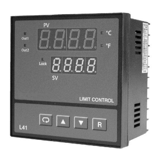
1-3 Programming Port and DIP Switch 1-3 Programming Port and DIP Switch Rear Front Terminal Panel ON DIP 1 2 3 4 Figure 1.1 Access Hole Figure 1.1 Access Hole Overview Overview Access Hole The programming port is used to connect to The programming port is used to connect to SNA12A for configuring with a PC. - Page 8 ENTER KEY 4 seconds, 6 seconds Press the scroll key for 4 seconds the display will enter the setup menu. Press this key for 6 seconds to enter the calibration mode. UP KEY This key is used to increase the selected parameter value during the lock indicator is off.
- Page 9 DISPLAY FORM DISPLAY FORM Table 1-1 Display Form of Characters Table 1-1 Display Form of Characters : These characters are displayed differently. How to display a 5-digit number : How to display a 5-digit number : For a number with decimal point the display will be shifted one digit right: -199.99 will be displayed as -199.9, 4553.6 will be displayed as 4553 For a number without decimal point the display will be divided into two alternating phases:...
- Page 10 SENSOR BREAK DISPLAY SENSOR BREAK DISPLAY If a break is detected in the sensor circuit, the display will show: A-D FAILURE DISPLAY A-D FAILURE DISPLAY If failure is detected in the A-D converter circuit, the display will show: POWER UP SEQUENCE POWER UP SEQUENCE All segments of display and indicators are left off for 0.5 second.
- Page 11 Display program code of the product Lock for 1.5 seconds. The left diagram shows program no.5 with version 10. LIMIT CONTROL LIMIT CONTROL Display Date Code for 1.5 seconds. The left diagram shows Year 2006, Month February (2), Date 25'th. This means that the product is produced on Lock February 25'th, 2006.
-
Page 12: Menu Overview
1-5 Menu Overview 1-5 Menu Overview Setup Mode Setup Mode 4 sec. 2 sec. PV Value Calibration Mode SP1 or SAFE Input type INPT INPT High limit H S P 1 UNIT UNIT Process unit setpoint 1 value Display resolution RESO RESO Low scale value for linear... -
Page 13: Limit Control Operation
1-6 Limit Control Operation 1-6 Limit Control Operation HIGH LIMIT OPERATION HIGH LIMIT OPERATION If Hi. is selected for OUT1, the unit will perform high limit control. When power is applied the OUT1 relay is de-energized. After 6.5 seconds self-test period, if the process is below the high limit set point (HSP1), the output 1 relay will be energized and OP1 indicator will go off. - Page 14 LOW LIMIT OPERATION LOW LIMIT OPERATION If Lo. is selected for OUT1, the unit will perform low limit control. When power is applied the OUT1 relay is de-energized. After 6.5 seconds self- test period, if the process is above the low limit set point (LSP1), the output 1 relay will be energized and OP1 indicator will go off.
- Page 15 HIGH/LOW LIMIT OPERATION HIGH/LOW LIMIT OPERATION If Hi.Lo is selected for OUT1, the unit will perform high/low limit control. When power is applied the OUT1 relay is de-energized. After 6.5 seconds self-test period, if the process is below the high limit set point (HSP1) and above the low limit set point (LSP1), the output 1 relay will be energized and OP1 indicator will go off.
-
Page 16: Parameter Descriptions
1-7 Parameter Descriptions 1-7 Parameter Descriptions Parameter Parameter Default Range Notation Description Value Low: HSP .L 100.0 C High Limit Set point 1 HSP1 High: HSP .H (212.0 F) Low: LSP .L Low Limit Set point 1 LSP1 High: LSP .H (32.0 F) Low: -19999 Set point 2 Value for... - Page 17 Parameter Parameter Default Range Notation Description Value : 4~20 mA linear current : 0~20 mA linear current : 0~60 mV linear voltage : 0~1 V Input Type Selection INPT ( 0 ) linear voltage : 0~5 V linear voltage : 1~5 V linear voltage : 0~10V linear voltage...
- Page 18 Parameter Parameter Default Range Notation Description Value High Scale Value for Low: IN.LO 100.0 IN.HI Linear Input High: 45536 Low: -200.0 C PV Shift ( offset ) (-360.0 F) SHIF High: 200.0 C Value (360.0 F) : 0 second time constant : 0.2 second time constant : 0.5 second...
- Page 19 Parameter Parameter Default Range Notation Description Value Low: 0.1 Output 1 Hysteresis O1.HY High: 10.0 C (18.0 F) Value Low: -19999 HSP .L Lower Limit of HSP1 High: HSP .H (32.0 F) Low: HSP .L 1000.0 C HSP .H Upper Limit of HSP1 High: 45536 (1832.0 F) Low: -19999...
- Page 20 Parameter Parameter Default Range Notation Description Value Address Assignment Low: 1 ADDR of Digital COMM High: 255 : 0.3 Kbits/s baud rate : 0.6 Kbits/s baud rate : 1.2 Kbits/s baud rate : 2.4 Kbits/s baud rate Baud Rate of Digital : 4.8 Kbits/s BAUD COMM...
- Page 21 Parameter Parameter Default Range Notation Description Value Low: -19999 100.0 C Analog Output High AOHI High: 45536 (212.0 F ) Scale Value : Process value high alarm AL.FN Alarm function : Process value low alarm : Normal alarm action AL.MD Alarm mode : Latching alarm action...
-
Page 22: Chapter 2 Installation
Chapter 2 Installation Chapter 2 Installation Dangerous voltages capable of causing death are sometimes present in this instrument. Before installation or beginning any troubleshooting procedures the power to all equipment must be switched off and isolated. Units suspected of being faulty must be disconnected and removed to a properly equipped workshop for testing and repair. -
Page 23: Wiring Precautions
2 - 3 Wiring Precautions 2 - 3 Wiring Precautions Before wiring, verify the label for correct model number and options. Switch off the power when checking. Care must be taken to ensure that maximum voltage rating specified on the label are not exceeded. It is recommended that power of these units to be protected by fuses or circuit breakers rated at the minimum value possible. -
Page 24: Power Wiring
2-4 Power Wiring 2-4 Power Wiring The controller is supplied to operate at 11-26 VAC / VDC or 90-250 The controller is supplied to operate at 11-26 VAC / VDC or 90-250 VAC. Check that the installation voltage corresponds with the power VAC. -
Page 25: Sensor Installation Guidelines
2-5 Sensor Installation Guidelines 2-5 Sensor Installation Guidelines Proper sensor installation can eliminate many problems in a control system. The probe should be placed so that it can detect any temperature change with minimal thermal lag. In a process that requires fairly constant heat output, the probe should be placed closed to the heater. -
Page 26: Rtd Input Wiring
2-7 RTD Input Wiring 2-7 RTD Input Wiring RTD connection are shown in Figure 2-6, with the compensating lead connected to terminal 19. For two-wire RTD inputs, terminals 19 and 20 should be linked. The three-wire RTD offers the capability of lead resistance compensation provided that the three leads are of same gauge and equal length. -
Page 27: Linear Dc Input Wiring
2-8 Linear DC Input wiring 2-8 Linear DC Input wiring DC linear voltage and linear current connections are shown in Figure 2-7 and 2-8. 0~60mV 0~60mV 0~60mV, 0~60mV, 0~1V, 0~5V, 0~1V, 0~5V, 1~5V, 0~10V. 1~5V, 0~10V. 0-1V, 0-5V 0-1V, 0-5V 1-5V, 0-10V 1-5V, 0-10V Figure 2-7... -
Page 28: Event Input Wiring
2-9 Event Input wiring 2-9 Event Input wiring Figure 2-9 Figure 2-9 Event Event Input Wiring Input Wiring he event input can accept a switch signal as well as an open collector signal. The event input function (EIFN) is activated as the switch is closed or an open collector (or a logic signal ) is pulled down. -
Page 29: Output 1 Wiring
2-10 Output 1 Wiring 2-10 Output 1 Wiring Figure 2-10 Figure 2-10 Output 1 Wiring Output 1 Wiring UM L41-Rev 2... - Page 30 UM L41-Rev 2...
- Page 31 UM L41-Rev 2...
- Page 32 If you use a conventional 9-pin RS-232 cable instead of CC94-1, If you use a conventional 9-pin RS-232 cable instead of CC94-1, the cable must be modified according to the following circuit the cable must be modified according to the following circuit diagram.
-
Page 33: Ma Retransmission
UM L41-Rev 2... -
Page 34: Chapter 3 Programming
Chapter 3 Programming Chapter 3 Programming Press for 4 seconds to enter setup mode. Press to select parameter. The display will indicate the parameter symbol and the value ( or selection ) for that parameter. INPT: Selects the sensor type and signal type for the process input. INPT: UNIT: Selects the process unit. -
Page 35: Setpoint Range
S-SL Formula: Formula: PV = IN.LO + ( IN.HI IN.LO ) SH-SL Example: a 4-20 mA current loop pressure transducer with range Example: 0 - 15 kg/cm , is connected to input, then perform the following setup: INPT = 4-20 mA IN.LO = 0.0 UNIT = PU IN.HI = 15.0... - Page 36 In certain application it is desirable to shift the indicated value from its actual value. This can be easily accomplished with this unit by using the PV shift function. Cycle the unit to the SHIF parameter by using the scroll key. The number you adjust here, either positive or negative, will be added to the actual value.
- Page 37 3-6 Process Alarms 3-6 Process Alarms The output 2 will perform process alarm function and PV.H.A or PV.L.A for AL.FN. If PV.H.A is selected the alarm will perform process high alarm. If PV.L.A is selected the alarm will perform process low alarm. The process alarm sets an absolute trigger level.
- Page 38 Examples: Examples: Examples: Examples: SP2 = 200 AL.HY = 10.0 AL.MD = NORM AL.FN = PV.H.A UM L41-Rev 2...
- Page 39 The controllers support RTU mode of Modbus protocol for the data Modbus communication. Other protocols are not available for the series. If you use a conventional 9-pin RS-232 cable instead of CC94-1, the If you use a conventional 9-pin RS-232 cable instead of CC94-1, the cable should be modified for proper operation of RS-232 cable should be modified for proper operation of RS-232 communication according to Section 2-9.
- Page 40 Typical use of an isolated DC power in unit to external transmitters/sensors is shown. Options are 20VDC rated at 25mA, 12VDC rated at 40 mA and 5VDC rated at 80 mA. The DC voltage is delivered to the output 2 terminals by selecting DCPS for OUT2 in setup menu.
- Page 41 If LOCK is selected for EIFN, terminals 16 & 17 will act as remote lock input. Turning the remote lock switch on will keep all the parameter setting from been changed. If the switch is opened the lock indicator is extinguished and the up/down key is enabled.
- Page 42 Chapter 5 Calibration Chapter 5 Calibration UM L41-Rev 2...
- Page 43 Normal Mode Figure 4-1 Figure 4-1 4 seconds Flow Chart for Manual Flow Chart for Manual Calibration Calibration RESET RESET Setup Mode 2 seconds RESET RESET Step 1 4 seconds RESET RESET Step 2 4 seconds RESET RESET Step 3 CJTL 4 seconds RESET...
- Page 44 Step 2: Calibrate Gain of A to D converter. ADG Calibration Gain Send a span signal to terminal 4 and 5 with correct polarity. The span signal is 60 mV for thermocouple input, 1V for 0-1V input, 10V for 0-10V input and 20mA for 0-20 mA input. Press for at least 4 seconds.
- Page 45 Step 5: Calibrate RTD reference voltage. REF Calibration RTD reference voltage Send a 100 ohms signal to terminal 3, 4 and 5 according to Figure 5-3. Figure 5-3 100 ohms 10 10 Figure 4-3 Figure 4-3 RTD Calibration RTD Calibration Press for at least 4 seconds.
- Page 46 Chapter 5 Specifications Chapter 5 Specifications Power Power 90-250 VAC, 47-63 Hz, 10 VA, 5W maximum 11-26 VAC/VDC, 10 VA, 5W maximum Input Input Resolution: 18 bits Resolution: 18 bits Sampling: 5 times/second Sampling: 5 times/second Maximum Rating: -2 VDC minimum, 12 VDC maximum Maximum Rating: -2 VDC minimum, 12 VDC maximum (1 minute for mA input)
- Page 47 Event Input Event Input Logic Low: -10V minimum, 0.8V maximum. Logic Low: Logic High: 2V minimum, 10V maximum. Logic High: Functions: Remote reset, remote lockout. Functions: Output 1 / Output 2 Output 1 / Output 2 Relay Rating: 2A/240 VAC, Relay Rating: life cycles 200,000 for resistive load.
- Page 48 Analog Retransmission Analog Retransmission User Interface User Interface Dual 4-digit LED Displays Dual 4-digit LED Displays keypad: 4 keys keypad: 4 keys Programming Port: For automatic configuration. Programming Port: For automatic configuration. Communication Port: Connection to PC Communication Port: Connection to PC for supervisory control.
- Page 49 Display Error Error Description Corrective Action Symbol Code Communication error: bad function Correct the communication code software to meet the protocol requirements. Communication error: register Don't issue an over-range address out of range register address to the slave. Communication error: attempt Don't write a read-only data or a to write a read-only data or a protected data to the slave.
- Page 50 Table 5-1 Input Characteristics Table 5-1 Input Characteristics UM L41-Rev 2...
- Page 51 UM L41-Rev 2...
- Page 52 Future Design Controls, Inc. UM L41-Rev 2...
Need help?
Do you have a question about the LIMIT L41 and is the answer not in the manual?
Questions and answers