Advertisement
Quick Links
Owner's Manual & Safety Instructions
Save This Manual
operating, inspection, maintenance and cleaning procedures. Write the product's serial number in the
back of the manual near the assembly diagram (or month and year of purchase if product has no number).
Keep this manual and the receipt in a safe and dry place for future reference.
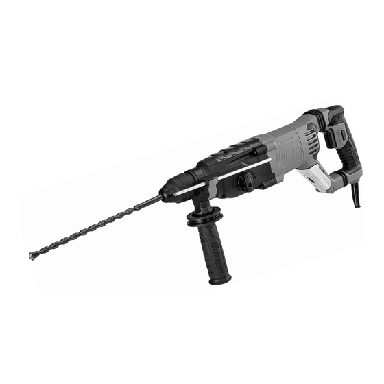
1" SDS-PLUS TYPE
ROTARY HAMMER
When unpacking, make sure that the product is intact
and undamaged. If any parts are missing or broken,
please call 1‑888‑866‑5797 as soon as possible.
©
Copyright
2021 by Harbor Freight Tools
No portion of this manual or any artwork contained herein may be reproduced in
any shape or form without the express written consent of Harbor Freight Tools.
Diagrams within this manual may not be drawn proportionally. Due to continuing
improvements, actual product may differ slightly from the product described herein.
Tools required for assembly and service may not be included.
Keep this manual for the safety warnings and precautions, assembly,
Visit our website at: http://www.harborfreight.com
email our technical support at: productsupport@harborfreight.com
®
. All rights reserved.
2142E-EB
Read this material before using this product.
Failure to do so can result in serious injury.
SAVE THIS MANUAL.
23i
58214
Advertisement

Related Manuals for Bauer 2142E-EB


Summary of Contents for Bauer 2142E-EB
- Page 1 (or month and year of purchase if product has no number). Keep this manual and the receipt in a safe and dry place for future reference. 2142E-EB 1" SDS-PLUS TYPE ROTARY HAMMER Visit our website at: http://www.harborfreight.com...
-
Page 2: Table Of Contents
table of contents Safety ............2 Maintenance ..........11 Specifications ..........8 Parts List and Diagram ......14 Setup ............8 Warranty ............ 16 Operation ............ 9 WarninG SyMBOLS anD DeFinitiOnS This is the safety alert symbol. It is used to alert you to potential personal injury hazards. -
Page 3: Safety
2. electrical safety f. Dress properly. Do not wear loose clothing or jewelry. Keep your hair, clothing a. power tool plugs must match the outlet. and gloves away from moving parts. never modify the plug in any way. Do not use Loose clothes, jewelry or long hair any adapter plugs with earthed (grounded) can be caught in moving parts. - Page 4 4. power tool use and care c. Brace the tool properly before use. This tool produces a high output torque and without a. Do not force the power tool. use the correct properly bracing the tool during operation, loss power tool for your application. The correct of control may occur resulting in personal injury.
- Page 5 g. Post signs to warn workers about circulation to the hand, past hand injuries, the hazard and to inform them about nervous system disorders, diabetes, or required protective equipment. Raynaud’s Disease should not use this tool. If you feel any symptoms related to h.
- Page 6 Double insulated tools: tools with two prong plugs 1. Tools marked “Double Insulated” do not require grounding. They have a special double insulation system which satisfies OSHA requirements and complies with the applicable standards of Underwriters Laboratories, Inc., the Canadian Standard Association, and the National Electrical Code.
- Page 7 Symbology Read the manual before Double Insulated set‑up and/or use. WARNING marking Volts concerning Risk of Fire. Do not cover ventilation ducts. Alternating Current Keep flammable objects away. WARNING marking concerning Risk of Electric Shock. Amperes Properly connect power cord to appropriate outlet.
-
Page 8: Specifications
Specifications Electrical Rating 120 VAC / 60Hz / 8.5A No Load Speed 0 ‑ 1200 RPM Impact Rate 0 ‑ 5200 BPM Chuck Size 1″ SDS‑Plus Type Setup - Before use: read the entire iMpOrtant SaFety inFOrMatiOn section at the beginning of this manual including all text under subheadings therein before set up or use of this product. - Page 9 Operating instructions read the entire iMpOrtant SaFety inFOrMatiOn section at the beginning of this manual including all text under subheadings therein before set up or use of this product. Setting and testing tO preVent SeriOuS inJury FrOM acciDentaL OperatiOn: Make sure that the trigger is in the off-position and unplug the tool from its electrical outlet before performing any procedure in this section.
- Page 10 changing SDS type or SDS-plus type Drill Bits cautiOn! Wear heavy‑duty work gloves to 3. Release the Chuck. provide protection when inserting and removing 4. Check that the drill bit is secured in place. drill bits. Drill bits become very hot during use. It should not be able to be pulled out of the Chuck.
- Page 11 General instructions for use Masonry Drilling Operation 1. Adjust the Auxiliary Handle as needed. 6. Do not apply excessive force, allow the tool to do the work. 2. Set the Function by adjusting the Mode Selector to the desired setting. concrete Drilling tips: a.
-
Page 12: Maintenance
Maintenance and Servicing instructions procedures not specifically explained in this manual must be performed only by a qualified technician. tO preVent SeriOuS inJury FrOM acciDentaL OperatiOn: Make sure that the trigger is in the off-position and unplug the tool from its electrical outlet before performing any procedure in this section. - Page 13 troubleshooting problem possible causes Likely Solutions Tool will not start. 1. Cord not connected. 1. Check that cord is plugged in. 2. No power at outlet. 2. Check power at outlet. If outlet is unpowered, turn off tool and check circuit breaker. If breaker is tripped, make sure circuit is right capacity for tool and circuit has no other loads.
-
Page 14: Parts List And Diagram
parts List and Diagram parts List part Description part Description Rubber Cover Upper Clutch Set Circlip for Shaft Φ18.8xΦ2 Pendulum Rod Bearing Sleeve Needle Φ9xΦ12x10 Retaining Ring Bearing Sleeve Steel Ball Φ7.25 Bearing 16003 Locating Ring Gear I Spring Steel Ball SΦ3 Tapping Screw ST4x45 Circlip for Shaft Φ8 Gear Box... - Page 15 assembly Diagram Item 58214 For technical questions, please call 1-888-866-5797. Page 15...
-
Page 16: Warranty
Limited 90 Day Warranty Harbor Freight Tools Co. makes every effort to assure that its products meet high quality and durability standards, and warrants to the original purchaser that this product is free from defects in materials and workmanship for the period of 90 days from the date of purchase.
Need help?
Do you have a question about the 2142E-EB and is the answer not in the manual?
Questions and answers