Table of Contents
Advertisement
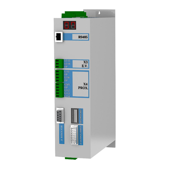
M.DRIVE.DB-21.GEN.ENG
INSTALLATION AND USE MANUAL
Ed.
2022
Rev.11
SERVO DRIVE TYPE – DB21
Pag.
1 di 34
INSTALLATION AND USE MANUAL
Servo Drive type DB-21
Suitable for turrets models:
Linea Archimede:
TB/TBMA/TBMR
Linea Michelangelo:
TAB
Linea Leonardo:
TC/TCMA/TCMR
Linea Galileo:
TBHMA-C/TBHMR-C
Linea Ecoline:
TBH/TBHMA
Advertisement
Table of Contents

Related Manuals for Baruffaldi DB21

Summary of Contents for Baruffaldi DB21
- Page 1 M.DRIVE.DB-21.GEN.ENG INSTALLATION AND USE MANUAL 2022 Rev.11 SERVO DRIVE TYPE – DB21 Pag. 1 di 34 INSTALLATION AND USE MANUAL Servo Drive type DB-21 Suitable for turrets models: Linea Archimede: TB/TBMA/TBMR Linea Michelangelo: Linea Leonardo: TC/TCMA/TCMR Linea Galileo: TBHMA-C/TBHMR-C Linea Ecoline:...
-
Page 2: Table Of Contents
7. WORKING LOGIC AND POSITIONING INQUIRY _______________________ 17 8. OPERATIVE MODE ___________________________________________ 18 9. DRIVE SET-UP (NEW TURRET INSTALLATION) ______________________ 19 10. DUTY CYCLE (BARUFFALDI/DIN5482 LIVE TOOL TOOLING SYSTEM) ____ 21 11. DUTY CYCLE (BMT/DIN5480/DIN1809 LIVE TOOL TOOLING SYSTEM) ____ 22 12. DRIVE ALARM _____________________________________________ 23 13. - Page 3 M.DRIVE.DB-21.GEN.ENG INSTALLATION AND USE MANUAL 2022 Rev.11 SERVO DRIVE TYPE – DB21 Pag. 3 di 34 GENERAL WARNINGS Before setting at work, carefully read instructions for use and follow them! Only qualified personnel, that has carefully read instructions, is allowed to operate on tool holder turrets.
-
Page 4: Safety And Installation
M.DRIVE.DB-21.GEN.ENG INSTALLATION AND USE MANUAL 2022 Rev.11 SERVO DRIVE TYPE – DB21 Pag. 4 di 34 1 SAFETY AND INSTALLATION SAFETY CONSIDERATION AND INSTALLATION CONSTRAINS It is important to ensure that cable and connection are carried out by a qualified technician. Wrong connections can cause damage to the device or generate dangerous situations for the user. - Page 5 M.DRIVE.DB-21.GEN.ENG INSTALLATION AND USE MANUAL 2022 Rev.11 SERVO DRIVE TYPE – DB21 Pag. 5 di 34 ►It is advisable to install the power parts of the motor control unit (drive, transformer, filters and resistances) in metallic divisions separate from those assigned to command and control devices. If the power supplies of the power groups are the same as the control apparatus, they should be connected in the same position (entrance point of the electronic device) in a star configuration.
-
Page 6: Specifications
M.DRIVE.DB-21.GEN.ENG INSTALLATION AND USE MANUAL 2022 Rev.11 SERVO DRIVE TYPE – DB21 Pag. 6 di 34 SPECIFICATIONS PARAMETERS 3x230V Power supply 3x400V +10/-15% 50÷60Hz 2KW Logic power supply 24VDC ±10% Nominal Current 6Arms SPWM, chopper frequency Method of current 3÷10 KHz... -
Page 7: Electrical Connections
M.DRIVE.DB-21.GEN.ENG INSTALLATION AND USE MANUAL 2022 Rev.11 SERVO DRIVE TYPE – DB21 Pag. 7 di 34 2. ELECTRICAL CONNECTIONS (INPUT) shielded cable POWER SUPPLY Power net (L1-L2-L3) Voltage option 1: 230Vac 3 phase +10/-15% Voltage option 2: 400Vac 3 phase +10/-15%... -
Page 8: Drive And Turret Layout
M.DRIVE.DB-21.GEN.ENG INSTALLATION AND USE MANUAL 2022 Rev.11 SERVO DRIVE TYPE – DB21 Pag. 8 di 34 3. DRIVE AND TURRET LAYOUT Software supervisior only for Service support RS485 shielded cable shielded cable shielded cable shielded cable shield ground The using of auxilliary relais between the... -
Page 9: Turret Connections
M.DRIVE.DB-21.GEN.ENG INSTALLATION AND USE MANUAL 2022 Rev.11 SERVO DRIVE TYPE – DB21 Pag. 9 di 34 4. TURRET CONNECTIONS 4.1 LINEA ARCHIMEDE – TB/TBMA/TBMR/TBYA/TBYR (STANDARD ELECTRICAL BOARD ON THE TURRET) LINEA ECO-LINE – TBH/TBHMA (STANDARD ELECTRICAL BOARD ON THE TURRET) -
Page 10: Linea Archimede - Tbmr/Tbyr (Harting Connector)
M.DRIVE.DB-21.GEN.ENG INSTALLATION AND USE MANUAL 2022 Rev.11 SERVO DRIVE TYPE – DB21 Pag. 10 di 34 4.2 LINEA ARCHIMEDE – TBMR/TBYR (HARTING CONNECTOR) Power supply 220Vac +10/-15% 400Vac +10/-15% =2KVA (Shielded Cable) Protection device RCD (with differential protection I = 300mA) -
Page 11: Linea Michelangelo - Tab (Standard Electrical Board On The Turret)
M.DRIVE.DB-21.GEN.ENG INSTALLATION AND USE MANUAL 2022 Rev.11 SERVO DRIVE TYPE – DB21 Pag. 11 di 34 4.3 LINEA MICHELANGELO - TAB (STANDARD ELECTRICAL BOARD ON THE TURRET) Power supply 220Vac +10/-15% 400Vac +10/-15% =2KVA (Shielded Cable) Protection device RCD (with... -
Page 12: Linea Leonardo - Tc/Tcma/Tcmr/Tcmq (Standard With Plug-In Connectors)
M.DRIVE.DB-21.GEN.ENG INSTALLATION AND USE MANUAL 2022 Rev.11 SERVO DRIVE TYPE – DB21 Pag. 12 di 34 4.4 LINEA LEONARDO – TC/TCMA/TCMR/TCMQ (STANDARD PLUG-IN CONNECTORS) WITH Power supply 220Vac +10/-15% 100b – Motor Connector Resolver 400Vac +10/-15% =2KVA 100c – Motor Connector Power... -
Page 13: J1 Input/Output
M.DRIVE.DB-21.GEN.ENG INSTALLATION AND USE MANUAL 2022 Rev.11 SERVO DRIVE TYPE – DB21 Pag. 13 di 34 5. J1 INPUT/OUTPUT OUTPUT INPUT +24VDC – MAX 100Ma +24VDC – MAX 100Ma DESCRIPTION DESCRIPTION Feedback bit 1 Mode bit 1 Feedback bit 2... -
Page 14: Operative Mode
M.DRIVE.DB-21.GEN.ENG INSTALLATION AND USE MANUAL 2022 Rev.11 SERVO DRIVE TYPE – DB21 Pag. 14 di 34 5.5 OPERATIVE MODE 5.6 POSITION REQUIRED It is recommended to manage the parity bit using the Boolean function EXOR (available in all PLCs) applied to the position bit. -
Page 15: Dipswitch Setting (For Turret Type Selection)
M.DRIVE.DB-21.GEN.ENG INSTALLATION AND USE MANUAL 2022 Rev.11 SERVO DRIVE TYPE – DB21 Pag. 15 di 34 6. DIPSWITCH SETTING (FOR TURRET TYPE SELECTION) 1 2 3 4 5 6 7 8 9 10 Dipswitch TURRET TB-TBH-TC Profile N° pos MODEL TB-TBH-TC 120/160 Univ. - Page 16 M.DRIVE.DB-21.GEN.ENG INSTALLATION AND USE MANUAL 2022 Rev.11 SERVO DRIVE TYPE – DB21 Pag. 16 di 34 DYNAMIC PROFILE It is possible to optimize the dynamic response of the drive according to the real load condition and unbalance applied to the turret.
-
Page 17: Working Logic And Positioning Inquiry
M.DRIVE.DB-21.GEN.ENG INSTALLATION AND USE MANUAL 2022 Rev.11 SERVO DRIVE TYPE – DB21 Pag. 17 di 34 7. WORKING LOGIC AND POSITIONING INQUIRY During the start it is important that the operative mode 1 (see chapter 5) is selected so any possible alarm will be displayed. -
Page 18: Operative Mode
M.DRIVE.DB-21.GEN.ENG INSTALLATION AND USE MANUAL 2022 Rev.11 SERVO DRIVE TYPE – DB21 Pag. 18 di 34 8. OPERATIVE MODE By setting the bit on the J2 connector you can select one of the following operatives mode: MODE 0 - RESET/ EMERGENCY [Li.1, Li.2, Li.3 = Off] The operative mode n°2-3-... -
Page 19: Drive Set-Up (New Turret Installation)
M.DRIVE.DB-21.GEN.ENG INSTALLATION AND USE MANUAL 2022 Rev.11 SERVO DRIVE TYPE – DB21 Pag. 19 di 34 9. DRIVE SET-UP (NEW TURRET INSTALLATION) INPUT VOLTAGE CAREFULLY CHECK THE SERVO DRIVE SETTING. A WRONG SETTING OF THE INPUT VOLTAGE WOULD DAMAGE IRREVERSIBLY THE UNIT. - Page 20 20 di 34 *The drive arrives pre-set for the turret. Perform this procedure only Sequence of operations N°3* in case of any error, and contacting Baruffaldi first 1. Drive OFF (24Vdc Off) 2. Turret Locked on the first position 4. Select the turret voltage (see operations sequence 1.) , type...
-
Page 21: Duty Cycle (Baruffaldi/Din5482 Live Tool Tooling System)
M.DRIVE.DB-21.GEN.ENG INSTALLATION AND USE MANUAL 2022 Rev.11 SERVO DRIVE TYPE – DB21 Pag. 21 di 34 10. DUTY CYCLE BARUFFALDI/DIN5482 LIVE TOOL TOOLING SYSTEM) -
Page 22: Duty Cycle (Bmt/Din5480/Din1809 Live Tool Tooling System)
M.DRIVE.DB-21.GEN.ENG INSTALLATION AND USE MANUAL 2022 Rev.11 SERVO DRIVE TYPE – DB21 Pag. 22 di 34 11. DUTY CYCLE (BMT/DIN5480/DIN1809 LIVE TOOL TOOLING SYSTEM) -
Page 23: Drive Alarm
M.DRIVE.DB-21.GEN.ENG INSTALLATION AND USE MANUAL 2022 Rev.11 SERVO DRIVE TYPE – DB21 Pag. 23 di 34 12. DRIVE ALARM In the table the CODE field is the sum of all bits of alarm active. Example: All.7.0 Time out rotation When malfunctioning occurs:... -
Page 24: Service
M.DRIVE.DB-21.GEN.ENG INSTALLATION AND USE MANUAL 2022 Rev.11 SERVO DRIVE TYPE – DB21 Pag. 24 di 34 13. SERVICE 13.1 TROUBLESHOOTING Display Description Code Undervoltage (only with turret unlocked) The power supply voltage on the M1 - Check with a multimeter the voltage on the L1-L2- connector is less than selected voltage L3 connector. - Page 25 M.DRIVE.DB-21.GEN.ENG INSTALLATION AND USE MANUAL 2022 Rev.11 SERVO DRIVE TYPE – DB21 Pag. 25 di 34 During locking the turret stays unlocked [Li.12=On, Li.13=Off] After 30” from the locking command - Check the functionality of proximity switch. (Lo.16) there isn’t the signal from the lock - Check the hydraulic/pneumatic circuit proximity switch (Li.13) and the turret...
- Page 26 M.DRIVE.DB-21.GEN.ENG INSTALLATION AND USE MANUAL 2022 Rev.11 SERVO DRIVE TYPE – DB21 Pag. 26 di 34 Time out rotation After to call a zero research (hidden too) - Check the functionality of zero proximity switch Zero proximity switch (Li.14) is always Off...
-
Page 27: Compatibility With Prevuious Versions
The installation of the new drive on CNC instead of a drive of previous versions to the model DMS08BF requires rewiring the connector J1 or the adoption of an adapter DB37 to DB26: ask details and price to Baruffaldi service or commercial department. -
Page 28: Drive Replacement (Set-Up And Setting)
M.DRIVE.DB-21.GEN.ENG INSTALLATION AND USE MANUAL 2022 Rev.11 SERVO DRIVE TYPE – DB21 Pag. 28 di 34 13.3 DRIVE REPLACEMENT (SET-UP AND SETTING) This procedure is used to change the setting of the drive in order to use it with all turrets type and motor produced. - Page 29 M.DRIVE.DB-21.GEN.ENG INSTALLATION AND USE MANUAL 2022 Rev.11 SERVO DRIVE TYPE – DB21 Pag. 29 di 34 Sequence of operations N°2 (VOLTAGE SETTING) 1. Drive OFF (24Vdc Off) 2. Set OFF dipswitch n°6 if the input voltage is 400V, set ON dipswitch n°6 if input voltage 1 2 3 4 5 6 7 8 9 10 is 230V.
- Page 30 M.DRIVE.DB-21.GEN.ENG INSTALLATION AND USE MANUAL 2022 Rev.11 SERVO DRIVE TYPE – DB21 Pag. 30 di 34 3. Switch ON the drive 4. Check on the display if the drive setup correctly. The display will flash for 10 seconds shown: - as a first indication the turret series and motor setup...
-
Page 31: Motor Replacement For Linea Archimede (Tb/Tbma/Tbmr) And Linea Ecoline (Tbh/Tbhma)
This operation must be carried out with locked turret in POSITION 1 no pressure in all circuits and motor+drive power off! Instructions below refer to turrets equipped with Baruffaldi motor; for different motors, please contact our Technical Department. ➢ Disassembling the motor Lock the turret on the 1 position and Power OFF the machine, the hydraulic pressure must be zero. -
Page 32: Motor Replacement For Linea Leonardo (Tc/Tcma/Tcmr/Tcmq)
This operation must be carried out with locked turret in POSITION 1 no pressure in all circuits and motor+drive power off! Instructions below refer to turrets equipped with Baruffaldi motor; for different motors, please contact our Technical Department. ➢ Disassembling the motor Lock the turret on the 1 position and Power OFF the machine, the hydraulic pressure must be zero. -
Page 33: Resolver Acquisition For Linea Archimede (Tb/Tbma/Tbmr) / Linea Ecoline (Tbh/Tbhma)/ Linea Leonardo (Tc/Tcma/Tcmr/Tcmq)
M.DRIVE.DB-21.GEN.ENG INSTALLATION AND USE MANUAL 2022 Rev.11 SERVO DRIVE TYPE – DB21 Pag. 33 di 34 13.6 RESOLVER ACQUISITION FOR L (TB/TBMA/TBMR) / L (TBH/TBHMA)/ L INEA RCHIMEDE INEA COLINE INEA EONARDO (TC/TCMA/TCMR/TCMQ) With this operation will be stored in the drive the value of the resolver when the turret is in position 1, this value will be used to verify that the required station is reached by the turret at the end zero research (also hidden zero research). -
Page 34: Cable Adapter For Old Drive Interfacing
14 CABLE ADAPTER FOR OLD DRIVE INTERFACING The installation of the new drive (Model DB-21) on CNC instead of the previous versions* requires rewiring the connector J1 or the adoption of an adapter DB37 to DB26: ask details and price to Baruffaldi service or sales department.
Need help?
Do you have a question about the DB21 and is the answer not in the manual?
Questions and answers