Table of Contents
Advertisement
Quick Links
M.DRIVE.DB-21.GEN.ENG
INSTALLATION AND USE MANUAL
Ed.
2021
Rev.04
SERVO DRIVE TYPE – DB21
Pag.
1 di 31
INSTALLATION AND USE MANUAL
Servo Drive type DB-21
Suitable for turrets models:
Linea Archimede:
TB/TBMA/TBMR
Linea Michelangelo: TAB
Linea Leonardo:
TC/TCMA/TCMR
Linea Galileo:
TBHMA-C/TBHMR-C
Linea Ecoline:
TBH/TBHMA
Advertisement
Table of Contents

Related Manuals for Baruffaldi DB-21

Summary of Contents for Baruffaldi DB-21
- Page 1 M.DRIVE.DB-21.GEN.ENG INSTALLATION AND USE MANUAL 2021 Rev.04 SERVO DRIVE TYPE – DB21 Pag. 1 di 31 INSTALLATION AND USE MANUAL Servo Drive type DB-21 Suitable for turrets models: Linea Archimede: TB/TBMA/TBMR Linea Michelangelo: TAB Linea Leonardo: TC/TCMA/TCMR Linea Galileo: TBHMA-C/TBHMR-C...
-
Page 2: Table Of Contents
7. WORKING LOGIC AND POSITIONING INQUIRY _______________________ 15 8. OPERATIVE MODE ___________________________________________ 16 9. DRIVE SET-UP (NEW TURRET INSTALLATION) ______________________ 17 10. DUTY CYCLE (BARUFFALDI LIVE TOOL TOOLING SYSTEM) ____________ 19 11. DUTY CYCLE (BMT/DIN5480/DIN1809 LIVE TOOL TOOLING SYSTEM) ____ 20 12. DRIVE ALARM _____________________________________________ 21 13. - Page 3 M.DRIVE.DB-21.GEN.ENG 2021 Rev.04 Pag. 3 di 31 GENERAL WARNINGS Before setting at work, carefully read instructions for use and follow them! Only qualified personnel, that has carefully read instructions, is allowed to operate on tool holder turrets. Responsibility and warranty are excluded if: Instructions for use are not followed.
-
Page 4: Safety And Installation
M.DRIVE.DB-21.GEN.ENG 2021 Rev.04 Pag. 4 di 31 1 SAFETY AND INSTALLATION SAFETY CONSIDERATION AND INSTALLATION CONSTRAINS It is important to ensure that cable and connection are carried out by a qualified technician. Wrong connections can cause damage to the device or generate dangerous situations for the user. -
Page 5: Specifications
M.DRIVE.DB-21.GEN.ENG 2021 Rev.04 Pag. 5 di 31 SPECIFICATIONS PARAMETERS 3x230V Power supply 3x400V +10/-15% 50÷60Hz 2KW Logic power supply 24VDC ±10% Current 4/16Arms SPWM, chopper frequency Method of current 3÷10 KHz control Torque control, speed Motor control method control, angular position control Clamp resistance 47Ω/50W... -
Page 6: Electrical Connections
M.DRIVE.DB-21.GEN.ENG 2021 Rev.04 Pag. 6 di 31 2. ELECTRICAL CONNECTIONS (INPUT) POWER SUPPLY Power net (L1-L2-L3) Voltage option 1: 220Vac 3 phase +10/15% Voltage option 2: 400Vac 3 phase +10/15% Pmin power transformer 2KVA 4Arms / 16Arms peak Class S3 Size cable Ømin=1,5mm2... -
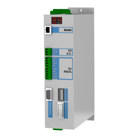
Page 7: Drive And Turret Layout
M.DRIVE.DB-21.GEN.ENG 2021 Rev.04 Pag. 7 di 31 3. DRIVE AND TURRET LAYOUT Software supervisior only for Service support RS485 shield ground... -
Page 8: Turret Connections
M.DRIVE.DB-21.GEN.ENG 2021 Rev.04 Pag. 8 di 31 4. TURRET CONNECTIONS 4.1 TB/TBH SERIES (STANDARD ELECTRICAL BOARD ON THE TURRET) Power supply 220Vac +10/15% 400Vac +10/15% =2KVA - T1 ELECTRICAL TERMINAL BLOCK – T2 ELECTRICAL TERMINAL BLOCK Auxiliary supply +24v 24Vdc ±10% Circuit consumption is 500mA. -
Page 9: Tb/Tbh Series (Harting Connector)
M.DRIVE.DB-21.GEN.ENG 2021 Rev.04 Pag. 9 di 31 4.2 TB/TBH SERIES (HARTING CONNECTOR) Power supply 220Vac +10/15% 400Vac +10/15% =2KVA - T1 HARTING CONNECTOR (FEMALE) Auxiliary supply +24v 24Vdc ±10% Circuit consumption is 500mA. Total consumption depend of relais/electrovalve THERMAL SWITCH Electrovalve LO.15... -
Page 10: Tab Series (Standard Electrical Board On The Turret)
M.DRIVE.DB-21.GEN.ENG 2021 Rev.04 Pag. 10 di 31 4.3 TAB SERIES (STANDARD ELECTRICAL BOARD ON THE TURRET) Power supply 220Vac +10/15% 400Vac +10/15% =2KVA - T1 ELECTRICAL TERMINAL BLOCK – T2 ELECTRICAL TERMINAL BLOCK Auxiliary supply +24v 24Vdc ±10% Circuit consumption is 500mA. -
Page 11: J1 Input/Output
M.DRIVE.DB-21.GEN.ENG 2021 Rev.04 Pag. 11 di 31 5. J1 INPUT/OUTPUT OUTPUT INPUT +24VDC – MAX 100Ma +24VDC – MAX 100Ma DESCRIPTION DESCRIPTION Feedback bit 1 Mode bit 1 Feedback bit 2 Mode bit 2 Feedback bit 3 Mode bit 3... -
Page 12: Operative Mode
M.DRIVE.DB-21.GEN.ENG 2021 Rev.04 Pag. 12 di 31 5.5 OPERATIVE MODE 5.6 POSITION REQUIRED It is recommended to manage the parity bit using the Boolean function EXOR (available in all PLCs) applied to the position bit. -
Page 13: Dipswitch Setting (For Turret Type Selection)
M.DRIVE.DB-21.GEN.ENG 2021 Rev.04 Pag. 13 di 31 6. DIPSWITCH SETTING (FOR TURRET TYPE SELECTION) TURRET SELECTION The setting of the turret type, the number of positions and dynamic profile must be performed before starting the drive (24Vdc). CUSTOM PROFILE For nonstandard applications can be set via software a specific profile setting manually the transmission ratio (T.R.), number of stations and dynamic profile, in this case a red label will be applies on the... - Page 14 M.DRIVE.DB-21.GEN.ENG 2021 Rev.04 Pag. 14 di 31 UNIVERSAL PROFILE FAST PROFILE Very soft acceleration Preferable when the inertia and deceleration is low. It allows to obtain ramps. Ideal for any positioning times lower. type of inertia. MEDIUM PROFILE Similar to the universal but with lower ramp rounding.
-
Page 15: Working Logic And Positioning Inquiry
M.DRIVE.DB-21.GEN.ENG 2021 Rev.04 Pag. 15 di 31 7. WORKING LOGIC AND POSITIONING INQUIRY During the start it is important that the operative mode 1 (see chapter 5) is selected so any possible alarm will be displayed. TURN ON THE CNC... -
Page 16: Operative Mode
M.DRIVE.DB-21.GEN.ENG 2021 Rev.04 Pag. 16 di 31 8. OPERATIVE MODE By setting the bit on the J2 connector you can select one of the following operatives mode: MODE 0 - RESET/ EMERGENCY [Li.1, Li.2, Li.3 = Off] The operative mode n°2-3- RESET duration ≥... -
Page 17: Drive Set-Up (New Turret Installation)
M.DRIVE.DB-21.GEN.ENG 2021 Rev.04 Pag. 17 di 31 9. DRIVE SET-UP (NEW TURRET INSTALLATION) INPUT VOLTAGE CAREFULLY CHECK THE SERVO DRIVE SETTING. A WRONG SETTING OF THE INPUT VOLTAGE WOULD DAMAGE IRREVERSIBLY THE UNIT. THE DRIVE ARRIVE WITH THE TURRET PRE-SET, PERFORM THE OPERATION SEQUENCE 2a AND 2b ONLY IN CASE OF WRONG PRESELECTION OF THE TURRET SIZE AND TYPE AND EVENTUALLY CONTACT BARUFFALDI. - Page 18 18 di 31 *The drive arrives pre-set for the turret. Perform this procedure only Sequence of operations N°2b* in case of any error, and contacting Baruffaldi first 1. Drive OFF (24Vdc Off) 2. Turret Locked on the first position 4. Select the turret voltage (see operations sequence 1.) , type...
-
Page 19: Duty Cycle (Baruffaldi Live Tool Tooling System)
M.DRIVE.DB-21.GEN.ENG 2021 Rev.04 Pag. 19 di 31 10. DUTY CYCLE BARUFFALDI LIVE TOOL TOOLING SYSTEM) -
Page 20: Duty Cycle (Bmt/Din5480/Din1809 Live Tool Tooling System)
M.DRIVE.DB-21.GEN.ENG 2021 Rev.04 Pag. 20 di 31 11. DUTY CYCLE (BMT/DIN5480/DIN1809 LIVE TOOL TOOLING SYSTEM) -
Page 21: Drive Alarm
M.DRIVE.DB-21.GEN.ENG 2021 Rev.04 Pag. 21 di 31 12. DRIVE ALARM When malfunctioning occurs: - are disabled the outputs ST INDEX, ST LOCK and POSITION FEEDBACK - the display shows the active alarm - are activated the alarm bit in the J1 connector (binary coded) In the table the CODE field is the sum of all bits of alarm active. -
Page 22: Service
(A0) Failed attempt to save data in EEPROM Contact Baruffaldi service (A1) EEPROM contains altered data Contact Baruffaldi service (A2) Absolute sensor alarm... - Page 23 M.DRIVE.DB-21.GEN.ENG 2021 Rev.04 Pag. 23 di 31 No signal from lock proximity switch [Li.12=Off, Li.13=Off] After 30” from the locking command - Check the functionality of proximity switch. (Lo.16) there isn’t the signal from the Remove the upper cover and verify that the lock proximity switch (Li.13) and the unlock...
- Page 24 M.DRIVE.DB-21.GEN.ENG 2021 Rev.04 Pag. 24 di 31 Zero proximity switch in short circuit The zero proximity (Li.14) is always On Check the functionality of zero proximity switch proximity Time out rotation (60”) Turret has not reached called position - Make sure there are no mechanical interferences within 60”...
-
Page 25: Compatibility With Prevuious Versions
The installation of the new drive on CNC instead of a drive of previous versions to the model DMS08BF requires rewiring the connector J1 or the adoption of an adapter DB37 to DB26: ask details and price to Baruffaldi service or commercial department. -
Page 26: Drive Replacement (Set-Up And Setting)
M.DRIVE.DB-21.GEN.ENG 2021 Rev.04 Pag. 26 di 31 13.3 DRIVE REPLACEMENT (SET-UP AND SETTING) This procedure is used to change the setting of the drive in order to use it with all turrets type and motor produced. Follow the timeline (chapter 13.2.1) for understand the correct setup to apply to the drive:... - Page 27 M.DRIVE.DB-21.GEN.ENG 2021 Rev.04 Pag. 27 di 31 Sequence of operations N°3: 1. Drive OFF (24Vdc Off) 2. Set all the dip switches OFF 3. Set ON the dipswitches according to the turret and the input voltage (see table below) 4. Turn ON the Drive 5.
- Page 28 M.DRIVE.DB-21.GEN.ENG 2021 Rev.04 Pag. 28 di 31 6. Switch the drive OFF and ON again, check on the display that the drive setup is correct. The display will flash for 4 seconds: first indication the turret series and motor setup, then as second indication the...
-
Page 29: Motor Replacement
M.DRIVE.DB-21.GEN.ENG 2021 Rev.04 Pag. 29 di 31 13.3 MOTOR REPLACEMENT Next sequence must be performed with machine turned OFF, no voltage in the circuit and without pressure in the air/hydraulic circuit. - Turret must be locked in the position n°1... -
Page 30: Zero Sensor Setting
M.DRIVE.DB-21.GEN.ENG 2021 Rev.04 Pag. 30 di 31 13.5 ZERO SENSOR SETTING In order to execute this procedure, it is necessary to supply the proximity switch (24Vdc) and have pressure in the lock/unlock turret circuit. - Supply the drive with only 24Vdc (X2 Input Connector) - Turret must be locked in position n°... -
Page 31: Cable Adapter For Old Drive Interfacing
13.6 CABLE ADAPTER FOR OLD DRIVE INTERFACING The installation of the new drive (Model DB-21) on CNC instead of the previous versions* requires rewiring the connector J1 or the adoption of an adapter DB37 to DB26: ask details and price to Baruffaldi service or sales department.
Need help?
Do you have a question about the DB-21 and is the answer not in the manual?
Questions and answers