
Related Manuals for Samson 3738-20


Summary of Contents for Samson 3738-20
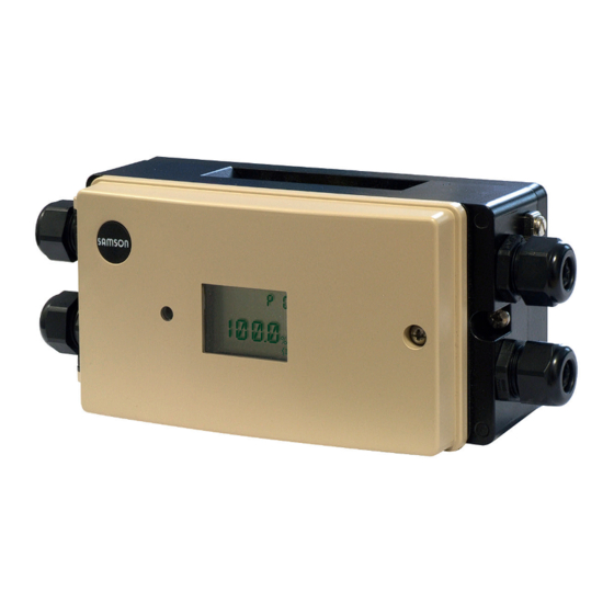
- Page 1 Type 3738-20 Electronic Limit Switch with optional integrated solenoid valve for on/off valves Mounting and Operating Instructions EB 8390 EN Firmware version 1.20 Edition June 2015...
- Page 2 Definition of signal words DANGER! NOTICE Hazardous situations which, if not Property damage message or mal- avoided, will result in death or seri- function ous injury Note: WARNING! Additional information Hazardous situations which, if not avoided, could result in death or seri- Tip: ous injury Recommended action...
-
Page 3: Table Of Contents
Connections ....................31 Pneumatic connections..................31 Supply pressure ...................32 Electrical connection ..................32 Operating controls and readings ..............36 Rotary pushbutton ..................36 SAMSON SSP interface ................36 Operating structure ..................37 Start-up ......................41 Adapting the display direction ..............41 Verifying readings on display................42 Determining the actuator type ...............43 Determining the direction of action ..............43... - Page 4 Contents Adjusting the limit switches ................44 Initialization ....................44 8.7.1 Start automatic initialization .................45 8.7.2 Start manual initialization ................46 Replacing an electronic limit switch ..............47 Zero/end position calibration ...............48 8.10 Reset to default settings .................48 Operation ....................49 Lock operation .....................49 Partial stroke test (PST) ..................49 9.2.1 Defining the PST target range ................51 9.2.2...
- Page 5 Firmware revisions Firmware Revisions 1.12 Changes to parameters and error messages (see section 13) • Parameters renumbered due to parameters being added or removed. Removed parameters: – 'PST initialization' (the partial stroke test no longer needs to be initialized). – Info: Rotary motions New parameters: – 'Actuator type' (rotary or linear actuator). See section 8.3.
- Page 6 Firmware revisions Firmware Revisions 1.20 Changes to parameter readings on the display • P3 Verify LCD segments: TSTD reading (see section 8.2) • P9 Automatic initialization: INIA reading (see section 8.7) • P10 Manual initialization: INIM reading (see section 8.7) • P11 End position calibration: REF reading (see section 8.9) • P17 Start manual PST: PST reading (see section 9.2) • P19 Testing contacts: TSTC reading (see section 9.3) • P20 Testing solenoid valve: TSTS reading (see section 9.4) • P21 Reset: RST reading (see section 8.10) New status message F15 This status message is generated when the configuration mode SET is activated. Changes to the partial stroke test (PST) (see section 9.2) A canceled partial stroke test (PST) is logged with a time stamp in TROVIS-VIEW.
-
Page 7: Important Safety Instructions
Important safety instructions 1 Important safety instructions For your own safety, follow these instructions concerning the mounting, start up and opera- tion of the electronic limit switch: − The device is to be mounted, started up or operated only by trained and experienced personnel familiar with the product. -
Page 8: Article Code
Article code 2 Article code Electronic Limit Switch Type 3738-20- x x x 1 x 0 0 x x x x 0 x With LCD Explosion protection Without 0 0 0 ATEX: II 2G Ex ia IIC T6; II 2D Ex IIIC T80°C IP66 1 1 0 ATEX: II 2G Ex eb[ia] IIC T4; II 2D Ex tb IIIC T80°C IP66 3 1 0 GOST: 1Ex ia IIC T6/T5/T4 Ga X; Ex tb IIIC T80°C Db X 1 1 3 GOST: 1Ex e [ia] IIC T4 Gb X; Ex tb IIIC T80°C Db X... -
Page 9: Design And Principle Of Operation
The electronic limit switch is designed for at- tachment to linear and rotary actuators. The The Type 3738-20 Electronic Limit Switch travel is measured without contact using a can replace conventional solenoid valves magnet (on a screw) positioned centrically and limit switches used for the automation of on the actuator shaft. - Page 10 15 NAMUR contact C (signal on reaching target range during Solenoid valve partial stroke test) Air capacity booster 16 NAMUR contact St (fault alarm contact) Display Fig. 2: Schematic diagram – Type 3738-20-xxx1400xxx000 Electronic Limit Switch with integrated solenoid valve EB 8390 EN...
- Page 11 Actuation of solenoid valve 15 NAMUR contact C (signal on reaching target range during Solenoid valve partial stroke test) Display 16 NAMUR contact St (fault alarm contact) Fig. 3: Schematic diagram – Type 3738-20-xxx1000xxxx00 Electronic Limit Switch with external solenoid valve EB 8390 EN...
-
Page 12: Versions
The contacts can be configured as either NO ry Actuators. The need for additional pneu- or NC contacts. See Fig. 4 and section 8.5. matic connections is eliminated. NAMUR contact St Type 3738-20-xxx1000xxxx00 Electronic This contact is a NC contact. Limit Switch for external solenoid valve The electronic limit switch for an external so- 3.1 Versions lenoid valve allows switching capacities up to max. 18 W at 24 V DC, meaning all... -
Page 13: Communication
Operator Interface. The electronic limit switch has for this pur- Type 3738-20-xxx1000xxxx00 in combi- pose a SAMSON SSP interface to allow the nation with an external solenoid valve RS-232 or USB port of a computer to be connected to it over a serial interface adapt- The forwarding of the switching voltage for er cable. - Page 14 Design and principle of operation The function is suitable for use in safety-in- − The proper functioning of the display can strumented systems up to SIL 2 (single chan- be verified over P3 parameter (see sec- nel) and SIL 3 (redundant configuration) ac- tion 8.2). − The correct setting of all parameters must cording to IEC 61508.
-
Page 15: Technical Data
3738-20-xxx1000xxxx00 Version With integrated solenoid valve For external solenoid valve Permissible range of rotation Min.: 0 to 30° Max.: 0 to 170° Communica- Local communication SAMSON SSP interface with serial interface adapter tion Software TROVIS-VIEW with database module 3738-20 Supply air Supply pressure 2.4 to 8 bar Same as specifications of the solenoid valve manufacturer Air quality According to ISO 8573-1... - Page 16 Technical data Electronic Limit Switch Type 3738-20-xxx1400xxx000 3738-20-xxx1000xxxx00 Version With integrated solenoid valve For external solenoid valve Safety ap- Safety-related end po- The limit switches are suitable for use in safety-instrumented proval sition monitoring systems up to SIL 2 (single channel) and SIL 3 (redundant con- figuration) according to IEC 61508. For further details, see section 3.3. Emergency venting Same as specifications of the See section 3.3...
- Page 17 Technical data Electronic Limit Switch Type 3738-20-xxx1400xxx000 3738-20-xxx1000xxxx00 Version With integrated solenoid valve For external solenoid valve Contacts Contact C PTO (power to open): responds when the valve moves through the switching contact towards the operating position (P14) Limit contact for inter-...
- Page 18 Technical data Table 1: Explosion protection certificates for Type 3738-20 Electronic Limit Switch Type Certification Type of protection EC type PTB 08 ATEX 2039 X II 2G Ex ia IIC T6; examination II 2D Ex ia IIIC T80°C IP66 Date 2012-02-02 certificate RU C-DE.08.B.00114 Date 2013-11-15 1Ex ia IIC T6/T5/T4 Ga X; Ex tb IIIC T80°C Db X Valid un- 2018-11-14 EC type PTB 08 ATEX 2039 X II 2G Ex eb[ia] IIC T4; examination II 2D Ex tb IIIC T80°C IP66...
-
Page 19: Solenoid Valve
Signal 0 When the voltage falls below 15 V DC Signal 1 Min. 18 V DC Switching capacity 24 V DC; 15.2 mA (0.36 W) Duty cycle 100 % Static destruction limit 32 V DC External solenoid valve (Type 3738-20-xxx1000xxxx00 Electronic Limit Switch) Read manufacturer’s specifications. 24 V DC, max. 18 W Switching Signal 0 When the voltage falls below 15 V DC voltage Signal 1 Min. 18 V DC Static destruction limit 32 V DC EB 8390 EN... -
Page 20: Attachment
Attachment 5 Attachment NOTICE Observe the following instructions to DANGER! avoid damaging the electronic limit − Electrostatic charging switch: Due to the high surface resistance − Use only the accessories listed in of the enclosure cover (R ≥ Isol. the Table 3 to mount the electronic Ω), installation and mainte- limit switch. -
Page 21: Attachment To Linear Actuators
Preparations Version with external solenoid valve Version with integrated solenoid valve (Type 3738-20-xxx1000xxx00) (Type 3738-20-xxx1400xxx000) (Fig. 5) 1. Fasten the electronic limit switch (1) to 1. Insert the molded seal (3) into the sup- the support element (2) using the two port element (2) depending on the type... -
Page 22: Attachment
Attachment 5.1.2 Attachment Mounting to Type 3271 Actuators with 1400 and 2800 cm² actuator areas and Use the lever (5) underneath the support ele- with 200 mm rated travel (Fig. 7 2 ) ment (2) and the pin (6) on the lever to Fasten the follower plate (7.4) at the out- adapt the electronic limit switch to the linear er holes to the stem connector (9) of the actuator. - Page 23 Attachment Electronic limit switch Support element 2.1 Supply air port (SUPPLY) Screw Lever 5.1 Disk spring 5.2 Nut Follower pin 6.1 Washer 6.2 Nut 7.1 Follower plate 7.2 Washer 7.3 Screws 7.4 Follower plate 7.5 Screws Bracket 8.1 Pin 8.2 Screws Stem connector Fig. 7: Mounting the electronic limit switch on linear actuators EB 8390 EN...
-
Page 24: Attachment To Rotary Actuators
Attachment 5.2 Attachment to rotary actuators Fig. 8 The electronic limit switch is mounted on ro- tary actuators according to VDI/VDE 3845, level 1 (2010). The version with integrated solenoid valve can be directly mounted to a Pfeiffer Type 31b Rotary Actuator. Required accessories: see Table 3 page 30 EB 8390 EN... - Page 25 Attachment Versions with integrated solenoid valve Version for external solenoid valve (Type 3738-20-xxx1400xxx000) (Type 3738-20-xxx1000xxxx00) Actuator surface Actuator surface Shaft height B [mm] Distance between holes A [mm] 80/130 Fig. 8: Mounting to rotary actuators according to VDI/VDE 3845, level 1 (2010) EB 8390 EN...
-
Page 26: Preparations
50 mm shaft height: press the second Version with integrated solenoid valve molded seal (4) onto the air ducts under- (Type 3738-20-xxx1400xxx000) (Fig. 10) neath one of the distance pieces (5). 5. Remove the blanking plug on the supply Two mounting platforms are available for the air port (SUPPLY) of the mounting plat- attachment (Fig. 9):... - Page 27 Attachment Single-acting 3/2-way Double-acting 5/2-way Distance piece for attachment to rotary actuators with 50 mm shaft height Electronic limit switch Mounting platform Molded seal O-ring Molded seal Distance piece Fig. 10: Preparations for mounting the electronic limit switch with integrated solenoid valve EB 8390 EN...
- Page 28 Attachment 1. Attachment to rotary actuators with 20 Note concerning electronic limit or 30 mm shaft height: switches with integrated solenoid Place the spacers (11) on the inner holes valve: of the actuator. Fasten the mounting platform (2), Attachment to rotary actuators with making sure that the air ducts located 50 mm shaft height: on the rotary actuator and the...
- Page 29 Attachment EB 8390 EN...
-
Page 30: Accessories
Stainless steel 1.1305 8808-0160 Version for Ex i: black plastic 8808-0180 Version for Ex i: blue plastic 8808-0181 TROVIS-VIEW Configuration TROVIS-VIEW with device module 3738-20 (free download from and Operator Interface soft- www.samson.de) ware Serial interface adapter (SAMSON SSP interface to 1400-7700 RS-232 port on a computer) Isolated USB interface adapter (SAMSON SSP interface... -
Page 31: Connections
− Operation with external solenoid hands or fingers. valve (Type 3738-20-xxx1000xxxx00) 6.1 Pneumatic connections The input pressure must not exceed the maximum supply pressure of the external solenoid valve (refer to the... -
Page 32: Supply Pressure
6.2 Supply pressure The maximum permissible values specified in the EC type examination Version with integrated solenoid valve certificate apply when connecting (Type 3738-20-xxx1400xxx000) the intrinsically safe circuits. Depending on the mounting platform used Adhere to the terminal assignment (ISO 228/1–G ¼ or ¼–18 NPT), customary specified in the certificate. Switching... - Page 33 V1 (81/82) ylene) must not be smaller than or at the terminals V3 (81/82) 0.2 mm. The diameter of individ- (Type 3738-20-xxx1400xxx000). ual wires in a fine-stranded con- Only connect one pair ductor must not be smaller than of 81/82 terminals.
- Page 34 Connection of electronic limit switch: optionally V1 or V3 A, B, C, St – – Display Rotary pushbutton LED for – solenoid valve – – – SAMSON SSP interface Fig. 12: Electrical connection – Version for internal solenoid valve (Type 3738-20-xxx1400xxx000) EB 8390 EN...
- Page 35 Connection of external solenoid valve: V1, V2 Connection of electronic limit switch: A, B, C, St – – – Rotary pushbutton Display LED for – solenoid valve – – SAMSON SSP interface Fig. 13: Electrical connection – Version for external solenoid valve (Type 3738-20-xxx1000xxxx00) EB 8390 EN...
-
Page 36: Operating Controls And Readings
The SAMSON SSP interface is located un- derneath the housing cover. 7.1 Rotary pushbutton The local SAMSON SSP interface of the elec- tronic limit switch needs to be connected The rotary pushbutton ( ) is located under- over a serial interface adapter cable (see Ta- neath the housing cover. -
Page 37: Operating Structure
Operating controls and readings 7.3 Operating structure valve position exceeds the selected limit ('PST step end' ± ½ 'PST tolerance band' (P14 ± The P2 parameter allows the user to switch ½ P15). It is possible to monitor the PST tar- between the RUN operating mode and SET get range when the P12 parameter (status configuration mode. In the SET configuration... - Page 38 Operating controls and readings Table 4: Indication of operating states Contacts A, B, C can configured as required (NC or NO contact) Contact St is always a NC contact Possible operating states in SET configuration mode Device not initialized/default settings ž ž ž ž Device initialized, fail-safe position ž š ž ž Device initialized, operating position š...
- Page 39 Placing the electronic limit switch into operation using its default settings – Switching voltage must be applied. Initial reading Initial reading (electronic limit (electronic limit switch not initialized) switch initialized) P1: Reading Change to RUN direction mode [1234] Enter key number: P4: Actuator type If the wrong key [ROT]...
- Page 40 Changing the operating mode and parameter settings Initial reading Initial reading (electronic limit (electronic limit switch initialized) switch initialized) Return to RUN mode Enter key number: If the wrong key number is entered, the mode does not change. Enter key number: If the wrong key number is entered,...
-
Page 41: Start-Up
Start-up 8 Start-up Note: The current angle of rotation is set to WARNING! 0° by pressing the rotary pushbutton Mount the electronic limit switch, ( ). keeping the following sequence: − Mount the electronic limit switch on − The current angle of rotation is displayed the actuator. -
Page 42: Verifying Readings On Display
Start-up 8.2 Verifying readings on dis- play P3: Display reading 5 NOTICE For safety-instrumented systems, the display’s functioning must be tested. P3: Display reading 6 The display’s functioning is checked using the P3 parameter. P3: Display reading when the test has not been P3: Display reading 7 started When the test has... -
Page 43: Determining The Actuator Type
Start-up 8.3 Determining the actuator Turn g P5 type , P5 blinks Press g PTC (power to close)/PTO (power Turn The setting of the actuator type (rotary or lin- to open) ear actuator) is made using P4 parameter. Press to confirm direction of action and to exit the parameter. -
Page 44: Adjusting The Limit Switches
Start-up 8.6 Adjusting the limit switches Observe the assignment of contacts A and B depending on the direction of action A limit signal is issued by the limit switches (page 83). for fail-safe position (contact A) and for op- P7: Switching contact, erating position (contact B). -
Page 45: Start Automatic Initialization
Start-up button ( ). ESC appears on the dis- NOTICE play. After the electronic limit switch has Data saved in the electronic limit been mounted onto another actuator switch before the initialization can be or its mounting location has been restored by pressing the rotary push- changed and before re-initializing, button ( ) again. -
Page 46: Start Manual Initialization
Start-up After the initialization has been successfully P10: Display reading completed, the current valve position in % is when initialization indicated. has not been started The electronic limit switch is in the configura- tion mode (SET). After initialization To start operation, exit the configuration has started: mode (see page 40). P10: Initialization is The automatic initialization is automatically being prepared canceled if a fault occurs (ERR on the dis- play). -
Page 47: Replacing An Electronic Limit Switch
Start-up 8.8 Replacing an electronic Press and hold for six seconds. The sec- onds remaining until the position check starts limit switch appear on the display. An (old) electronic limit switch can be re- Display: POS1 placed by another (new) electronic limit Î... -
Page 48: Zero/End Position Calibration
Start-up 8.9 Zero/end position calibra- The error can be read in the ERR parameter level: tion − E6: Time-out When the zero point or end positions are in- − E8: Unable to calibrate end positions correct, it may be necessary to recalibrate them. -
Page 49: Operation
Operation Operation The following conditions must be met before the partial stroke test (PST) can be per- formed: WARNING! The actuator shaft/stem moves while − An automatic initialization must have the electronic limit switch is operat- been performed (see section 8.7.1). ing. − The switching voltage must be applied. Do not touch the actuator shaft/stem Test procedure (Fig. 16) or obstruct it to avoid risk of injury to... - Page 50 Start-up Direction of action PTO Contact C Contact C Contact B Contact B Contact B Contact B x [%] Contact SV off SV on Holding time Dead time t [s] PST duration PST start PST start PST start Direction of action PTC Contact C Contact C Contact B...
-
Page 51: Defining The Pst Target Range
Operation 9.2.1 Defining the PST target reached') and F7 ('Max. value for PST exceeded') are to be generat- range ed, the P12 parameter must be set to YES. Define the target range by configuring P14 and P15 parameters. − Contact C can be used to indicate a third switching position. -
Page 52: Starting The Partial Stroke Test
Operation 9.2.2 Starting the partial stroke test P17: Reading before the partial stroke test A single PST test can be started manually or starts a regular PST test can be started automati- cally at defined time intervals. After the partial stroke test starts: Start PST automatically at defined intervals P17: Start of PST is be- (RUN mode) ing prepared... -
Page 53: Example: Pto Direction Of Action
Operation 9.2.3 Example: PTO direction 2. Define PST target range (P14, P15) of action The PST target range is made up of the 'PST step end' (P14) and the 'PST toler- The valve is normally open (operating posi- ance band' (P15). The test has been suc- tion = 100 %). In the event of emergency, the cessfully completed when the valve valve is to close (fail-safe position = 0 %). - Page 54 Operation * The contact C remains activated three seconds after the valve moves out again of the PST target range. Fig. 17: Example: Course of first two partial stroke tests The graph shows the states when A, B and C contact setting = NC (P6) EB 8390 EN...
-
Page 55: Testing The Contacts
Operation 5. Select RUN operating mode (P2) Check the attachment and supply air line when the status message F9 ('Timeout The countdown starts after the electronic during PST') is generated. limit switch has been switched to the RUN operating mode (P2 = RUN). The last 10 evaluations are saved in a non-volatile memory in the electronic 6. -
Page 56: Testing The Solenoid Valve
Operation The electronic limit switch must be in the con- Press figuration mode (SET). See page 40. The contact selected is deactivated while the rotary pushbutton is pressed. Display when P6 = NC Turn g ESC P19: Reading before the Press to exit the parameter setting. -
Page 57: Faults
Operation Turn g Operating position Example: Turn to de-energize the solenoid valve F2: Limit of maximum (the valve moves to the fail-safe position) rotary motion (P26) while the rotary pushbutton is pressed. exceeded Turn g ESC Press to exit the parameter. Refer to the parameter list (section 13.1) for possible causes and the recommended ac- 9.5 Faults... -
Page 58: Confirming Status And Error Messages
, F0/…/F10, E1/…/E10 blinks Press Turn g RST Version with integrated solenoid valve Press to confirm status/error message. (Type 3738-20-xxx1400xxx000) There are filters with a 100 µm mesh size in the pneumatic connections for supply and output which can be removed and cleaned, 10 Maintenance, calibration if required. and work on equipment... -
Page 59: Firmware Update (Serial Interface)
Firmware updates on electronic limit switches currently in operation can be performed as follows: When updates are performed by a service employee appointed by SAMSON, the up- date is confirmed on the device by the test mark assigned by SAMSON’s Quality Assur- ance. In all other cases, only plant operator per- sonnel with written approval may perform updates. Updates are to be confirmed by ap-... -
Page 60: Parameter List
Parameter list 13 Parameter list Parameter – Readings, values [default setting] Description Parameters marked with an asterisk (*) can only be changed when the electronic limit switch is in the SET configuration mode (set in P2). Info: actual value After initialization: current valve position in % See sec- tion 8. Keep pressed down current valve position in ° (angle) - Page 61 Parameter list Parameter – Readings, values [default setting] Description Switching function of contacts NC contact See sec- A, B, C tion 8.5. NO contact [NC] · NO NX1 … NX6 Note: The contacts A, B and C can be individually configured in the TRO- VIS-VIEW software. This indicated on the display as NX1 … NX6. All the con- tacts are configured together as NC contact (1) or NO contact (2) by the on-site operation.
- Page 62 Parameter list Parameter – Readings, values [default setting] Description Partial stroke test (PST) The PST step range is limited between 2 and 98 % ('PST step end' ± ½ 'PST tolerance band') P14* PST step end Step end position that the valve is to be moved See sec- to during the PST. tion 9.2. 4.0 to 96.0 % · ESC If the partial stroke test is not used, a third [90.0 %] switching position can be indicated by contact P15*...
- Page 63 Parameter list Parameter – Readings, values [default setting] Description Reset function P21* Reset Resets all settings of electronic limit switch to the See sec- factory default settings. tion 8.10. RST · ESC Display functions · Read only Info: actuator transit time Time [s] required by the actuator to move to the –...
-
Page 64: Status Messages
Parameter list 13.1 Status messages Status message Possible causes Status messages marked with an asterisk (*) can be confirmed in SET configuration mode. See sec- tion 9.5.1. TROVIS-VIEW: Current status messages are saved with a time stamp in [Diagnostics – Status mes- sages]. • Mechanical blockage Stationary outside re- quired/desired end • Supply pressure too low positions • External leakage Recommended action • Check attachment and supply air line. • Incorrect voltage supplied to the solenoid valve Left end position with- out being required to... - Page 65 Parameter list Status message Possible causes • Mechanical blockage Actuator stationary when required to • Supply pressure too low move • External leakage Recommended action • Check attachment and supply air line. Note: If the valve moves after a delay, F5 remains active until the next successful switch- ing demand.
- Page 66 Parameter list Status message Possible causes See page 41 Configuration mode SET activated EB 8390 EN...
-
Page 67: Error Messages
Parameter list 13.2 Error messages Error message Possible causes Error messages marked with an asterisk (*) can be confirmed in SET configuration mode. See sec- tion 9.5.2. TROVIS-VIEW: The last 32 error messages are displayed with a time stamp in TROVIS-VIEW [Diagnostics – Logging of device errors]. • The electronic limit switch has not yet been initialized. Device not initialized Recommended action • Start initialization with P9 or P10 parameter. - Page 68 Device error • Internal error Device error 1 Recommended action • Restart the electronic limit switch (return it to SAMSON if er- ror repeatedly occurs). Note: When E9 is generated, the wire break (contact B_LB) is additionally signaled in accordance with DIN EN 60947-5-6.
-
Page 69: Dimensions In Mm
Dimensions in mm 14 Dimensions in mm EB 8390 EN... -
Page 70: Fixing Levels According To Vdi/Vde 3845 (September 2010)
Dimensions in mm 14.1 Fixing levels according to VDI/VDE 3845 (September 2010) Fixing level 2 (bracket surface) Fixing level 1 (actuator surface) Actuator Dimensions in mm Size Ød 5.5 for M5 5.5 for M5 5.5 for M5 ØD 5.5 for M5 5.5 for M5 6.5 for M6 * Flange type F05 according to DIN EN ISO 5211... - Page 71 EB 8390 EN...
- Page 72 EB 8390 EN...
- Page 73 EB 8390 EN...
- Page 74 EB 8390 EN...
- Page 75 EB 8390 EN...
- Page 76 EB 8390 EN...
- Page 77 EB 8390 EN...
- Page 78 Index Index Limit contacts ........44 Accessories .......... 30 Maintenance ........58 Article code ........... 8 Attachment Accessories ........30 Operating elements ......36 To linear actuators ......21 Operating structure ......37 To rotary actuators ......24 Operation ..........49 Lock ..........
- Page 79 Status messages ......57, 64 Supply ..........32 Supply pressure ........32 Switching function of contacts ....43 Technical data Electronic limit switch ...... 15 Solenoid valve ........ 19 Testing contacts ........55 Testing solenoid valve ......56 Wire break .......... 55 Zero calibration ........
- Page 80 EB 8390 EN...
- Page 81 Key number...
- Page 82 Info: firmware version Parameter list Status messages Info: actual value Reading direction Stationary outside required/desired end posi- tions Configuration: RUN/SET Left end position without being required to move Verify LCD segments (TSTD) Limit of P26 exceeded Actuator type Temperature limits exceeded Actuator's direction of action Actuator transit time exceeded Switching function of contacts A, B, C Actuator stationary when required to move...
-
Page 83: Assignment Based On The Direction Of Action
Assignment based on the direction of action Assignment based on the direction of action PTO (power to open) – Position Switching contact for end position Contact A P7 (0.5 to 96.0 %, [2.0 %]) Fail-safe position (0 %) · Valve CLOSED Contact B Operating position (100 %) · Valve P8 (4.0 to 99.5 %, [98.0 %]) OPEN PTC (power to close) – Position Switching contact for end position Contact A Fail-safe position (100 %) · Valve OPEN... - Page 84 SAMSON AG · MESS- UND REGELTECHNIK Weismüllerstraße 3 · 60314 Frankfurt am Main, Germany Phone: +49 69 4009-0 · Fax: +49 69 4009-1507 EB 8390 EN samson@samson.de · www.samson.de...
Need help?
Do you have a question about the 3738-20 and is the answer not in the manual?
Questions and answers