
Related Manuals for BTEK BT-470TL

Summary of Contents for BTEK BT-470TL
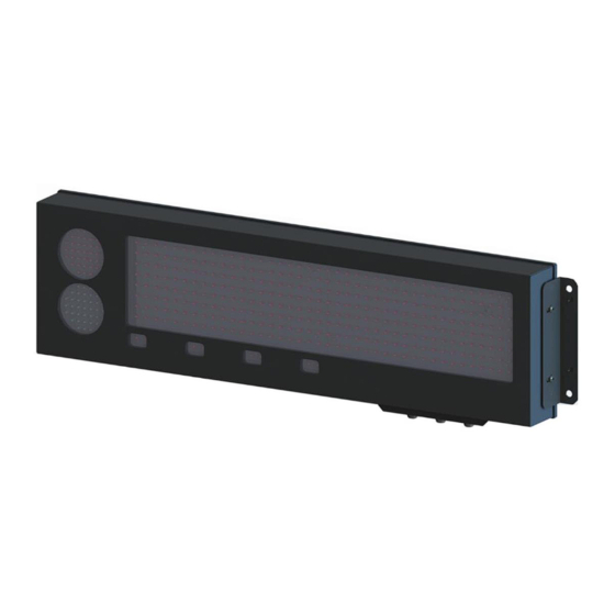
- Page 1 BT-470TL REMOTE DISPLAY Item# 841-100043 / 841-100044 OPERATION & SETUP GUIDE V1.0 Page | 1...
-
Page 2: Table Of Contents
Contents Introduction ..............................3 Downloads ..............................3 Wall and Pole Mounting ..........................4 Autolearn Mode ............................6 Embedded User Menu ..........................7 Factory Default ............................8 Connecting the Display to a Computer for Configuration Purposes.............. 9 WagSet (Windows Operating System only) ..................... 10 Web Panel Configuration Method...................... -
Page 3: Introduction
Introduction BT-470TL remote display is designed to display measurement results transmitted by weighing terminals. The display operates in the automatic mode by default (see Autolearn) and in standard installations does not require prior configuration. For advanced options, it is necessary to adjust the settings via WagSet software (from version v3.00), or through the user menu embedded in the device, or Web browser. -
Page 4: Wall And Pole Mounting
Wall Mounting The BT-470 Item# 841-100044 can be wall mounted by fastening the two angle brackets to the side of the display, then attaching to a sturdy wall. When installing without the visor, it is recommended to install in an area protected from direct sunlight and rain. Item# 841-100043 includes a visor, and pole mounting hardware. - Page 5 Pole Mounting The mounting rails are fitted directly to the rear part of the device housing with the screws included in the set. They enable the installation of mounting clamps, which are used to install the device on a pole. Two mounting rails are provided for each remote.
-
Page 6: Autolearn Mode
Autolearn Mode The autolearn mode is enabled by default (position no. 0 is set in the 'proto' submenu). To disable it, the communication protocol must be set manually using the embedded user menu or the WagSet software. When autolearn mode is active, each time the device is started, it detects the parameters of the communication with the weighing terminal and analyses the structure of the data frames it sends. -
Page 7: Embedded User Menu
Embedded User Menu The button used to operate the menu is located on the controller board inside the display housing and marked B1. To access, unscrew the two philips head screws and slide out the controller board drawer. Once you have finished the configuration, push the drawer back, making sure that the seal is not compromised. -
Page 8: Factory Default
“proto” option allows you to select the display communication protocol to work with the selected weighing terminals (Tab. 1). You can change the protocol by short pressing the button. Saving the selected protocol is accomplished by long holding down the button (until the messag "Saved"... - Page 9 List of the supported protocols Note: “Proto” 53 is the B-TEK string bold font, “Proto” 54 is B-TEK string normal font, “Custm” 28 is the Bilanciai Extended String. Note 2: B-TEK strings allow alpha characters to be displayed in place of weight data. Seq.
-
Page 10: Connecting The Display To A Computer For Configuration Purposes
Connecting the Display to a Computer for Configuration Purposes WagSet (Windows Operating System only) WagSet Software Download Before configuring the display from WagSet, connect it to a computer via Ethernet or RS232. When using RS232, connect to the port of the computer as shown in the fig. below. See “Remote Display Connections”... -
Page 11: Web Panel Configuration Method
Web Panel Configuration Method To access the web panel, follow the instructions below: 1. In the network card properties select “Internet Protocol Version 4 (TCP/IPv4), and click “Properties”. 2. In the “Internet Protocol Version 4 Properties”, select “Use the following IP address” option, and then complete the following fields: IP address: 192.168.1.55, Subnet mask: 255.255.255.0 and confirm changes. -
Page 12: Remote Display Connections
Remote Display Connections NOTICE! The controller board should only be accessed when the power supply is disconnected. Take special care when doing this because of the danger of electric shock. Connector Interface / Function Notes marking RxD line of the RS-232 interface. The line should be connected with the weighing terminal TXD output. -
Page 13: Ethernet Settings To Transmit Weight Data
Ethernet Settings to Transmit Weight Data • Default display IP is 192.168.1.11, default gateway to 192.168.1.1 • Default weighing terminal IP set to 192.168.1.12. Data port 2102. Select “Proto 53”, or “Proto 54” protocol, then send the B-TEK String for easy setup. When using these protocols, the indicator must be set as server, the remote is client. -
Page 14: Replacement Part Item Numbers
BRACKETS, & ANNUNCIATORS 841-100041 BT-470 4.7" LED ARRAY REMOTE DISPLAY w/ ANNUNCIATORS 841-100043 BT-470TL 4.7" LED ARRAY REMOTE DISPLAY w/VISOR, 3" POLE MNT BRACKETS, ANNUNCIATORS, & TRAFFIC LIGHT 841-100044 BT-470TL 4.7" LED ARRAY REMOTE DISPLAY w/ ANNUNCIATORS, & TRAFFIC LIGHT 841-500074 BT-470 4.7"...
Need help?
Do you have a question about the BT-470TL and is the answer not in the manual?
Questions and answers