Table of Contents
Advertisement
Available languages
Available languages
Operator's Manual
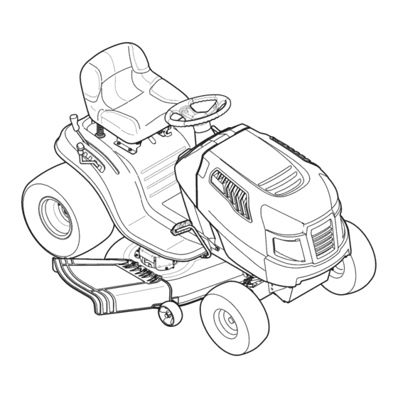
LAWN TRACTOR
19.5 HP, Variation Speed
42" Deck
Model No. 247.288843
• Espanol, P. 60
This product has a low emission engine which operates differently
from previously built engines. Before you start the engine, read and
understand this Operator's Manual.
CAUTION
Before using this equipment,
read this manual and follow
all safety rules and operating
instructions.
Sears Brands Management Corporation, Hoffman Estates, IL 60179 U.S.A.
Visit our website: www.craftsman.com
®
For answers to your questions about
this product, Call:
1-800-659-5917
Craftsman Tractor Help Line
7 am - 7 pm CT, Mon. - Sun.
Form No. 769-06421D
(November 28, 2012)
Advertisement
Chapters
Table of Contents

Related Manuals for Craftsman 247.288843


Summary of Contents for Craftsman 247.288843
- Page 1 ® LAWN TRACTOR 19.5 HP, Variation Speed 42” Deck Model No. 247.288843 • Espanol, P. 60 This product has a low emission engine which operates differently from previously built engines. Before you start the engine, read and understand this Operator’s Manual.
-
Page 2: Table Of Contents
WARRANTY SERVICE For warranty coverage details to obtain free repair or replacement, call 1-800-659-5917 or visit the web site: www.craftsman.com In all cases above, if part repair or replacement is impossible, the riding equipment will be replaced free of charge with the same or an equivalent model. -
Page 3: Safety Instructions
SAFETY INSTRUCTIONS WARNING DANGER This machine was built to be operated according to the safe opera- This symbol points out important safety instructions which, if not tion practices in this manual. As with any type of power equipment, followed, could endanger the personal safety and/or property of carelessness or error on the part of the operator can result in serious yourself and others. - Page 4 SAFETY INSTRUCTIONS SLOPE OPERATION • Slow down before turning. Operate the machine smoothly. Avoid erratic operation and excessive speed. Slopes are a major factor related to loss of control and tip-over • Disengage blade(s), set parking brake, stop engine and wait until accidents which can result in severe injury or death.
- Page 5 SAFETY INSTRUCTIONS CHILDREN SERVICE Tragic accidents can occur if the operator is not alert to the presence Safe Handling of Gasoline of children. Children are often attracted to the machine and the mowing To avoid personal injury or property damage use extreme care in activity.
- Page 6 SAFETY INSTRUCTIONS General Service • Do not change the engine governor settings or over-speed the engine. The governor controls the maximum safe operating speed • Never run an engine indoors or in a poorly ventilated area. Engine of the engine. exhaust contains carbon monoxide, an odorless, and deadly gas.
- Page 7 SAFETY INSTRUCTIONS SAFETY SYMBOLS This page depicts and describes safety symbols that may appear on this product. Read, understand, and follow all instructions on the machine before attempting to assemble and operate. Symbol Description READ THE OPERATOR’S MANUAL(S) Read, understand, and follow all instructions in the manual(s) before attempting to assemble and operate DANGER—...
-
Page 8: Slope Gauge
SLOPE GAUGE... -
Page 9: Assembly
ASSEMBLY IMPORTANT: Your tractor is shipped with motor oil in the engine. Shipping Brace Removal However, you MUST check the oil level before operating. Refer to the WARNING Service & Maintenance section for instructions on checking the oil Make sure the riding mower’s engine is off, remove the ignition key, level. - Page 10 ASSEMBLY Adjusting the Seat To adjust the position of the seat, pull up and hold the seat adjustment lever. Slide the seat forward or rearward to the desired position; then release the adjustment lever. Make sure seat is locked into position in a seat-stop before operating the tractor.
-
Page 11: Operation
NOTE: Any reference in this manual to the RIGHT or LEFT side of the tractor is observed from operator’s seat position facing forward towards the front of tractor. Meets ANSI Safety Standards Craftsman Tractors conform to the safety standard of the American National Standards Institute (ANSI). - Page 12 OPERATION Parking Brake Lever Seat Adjustment Lever To set the parking brake: Fully depress the brake pedal. Move the The seat adjustment lever is located below the front/left of the seat. The lever parking brake lever into the parking brake position. Release the allows for adjustment of the fore and aft position of the seat.
- Page 13 OPERATION Gas and Oil Fill-up IMPORTANT: Your tractor is shipped with motor oil in the engine. However, you MUST check the oil level before operating. Be careful not to overfill. For instructions on how to check the engine oil, refer to Checking The Engine Oil in the Service and Maintenance section of this manual.
- Page 14 OPERATION Setting the Cutting Height • The engine will automatically shut off if the PTO (Blade Engage) lever is moved into the engaged (ON) position with the shift lever in Reverse. Select the height position of the cutting deck by placing the deck lift lever in Ignition Switch any of the different cutting height notches on the right side of the fender.
- Page 15 OPERATION Driving The Tractor CAUTION Do NOT hold the key in the START position for longer than ten seconds WARNING at a time. Doing so may cause damage to your engine’s electric Avoid sudden starts, excessive speed and sudden stops. starter.
- Page 16 OPERATION Driving On Slopes Mowing Refer to the SLOPE GAUGE in the Safety Instructions section of the manual to help WARNING determine slopes where you may operate this tractor safely. To help avoid blade contact or a thrown object injury, keep bystanders, WARNING helpers, children and pets at least 75 feet from the machine while it is in operation.
-
Page 17: Service And Maintenance
SERVICE AND MAINTENANCE MAINTENANCE SCHEDULE WARNING Before performing any type of maintenance/service, disengage all controls Follow the maintenance schedule given below. This chart describes service and stop the engine. Wait until all moving parts have come to a complete guidelines only. Use the Service Log column to keep track of completed stop. - Page 18 SERVICE AND MAINTENANCE Engine Maintenance Changing Engine Oil The engine oil should be changed in the first 5 hours and then every 50 hours or Checking the Engine Oil once a season. To change the engine oil, proceed as follows: Only use high quality detergent oil rated with API service classification SF, SG, With engine OFF but still warm, disconnect spark plug wire and keep it away SH, or SJ.
- Page 19 SERVICE AND MAINTENANCE Fuel Filter Air Cleaner WARNING The air filter system uses a cylindrical cartridge. Remove the fasteners (A) and the air filter cover (B). See Figure 13. Gasoline and its vapors are extremely flammable and explosive. Fire or explosion can cause severe burns or death.
- Page 20 SERVICE AND MAINTENANCE Muffler re-installing the battery, always connect the POSITIVE (Red) wire to its terminal first, followed by the NEGATIVE (Black) wire. Be certain that the wires are connected WARNING to the correct terminals; reversing them could change the polarity and result in damage to your engine’s alternating system.
- Page 21 SERVICE AND MAINTENANCE Adjustments Side to Side If the cutting deck appears to be mowing unevenly, a side to side adjustment can be WARNING performed. Adjust if necessary as follows: Never attempt to make any adjustments while the engine is running, except With the tractor parked on a firm, level surface, place the deck lift lever in where specified in the operator’s manual.
- Page 22 SERVICE AND MAINTENANCE Cutting Deck Removal To remove the cutting deck, proceed as follows: Bow-Tie Clip Place the PTO (Blade Engage) lever in the disengaged (OFF) position and engage the parking brake. Lower the deck by moving the deck lift lever into the bottom notch on the right fender.
- Page 23 SERVICE AND MAINTENANCE Connect the other end of the cable to the (positive +) post of the jumper battery. Connect the second cable (negative –) to the other post of the jumper battery. Connect the other end of the negative cable to the engine block of the tractor, away from the battery.
- Page 24 SERVICE AND MAINTENANCE Cutting Blades CAUTION WARNING If the cutting edge of the blade has previously been sharpened, or if any metal separation is present, replace the blades with new ones. Shut the engine off and remove ignition key before removing the cutting blade(s) for sharpening or replacement.
- Page 25 SERVICE AND MAINTENANCE Changing the Transmission Drive Belt While holding the belt and pulley together, rotate the pulley to the left. Continue holding and rotating the pulley and belt until the belt is fully rolled NOTE: Several components must be removed and special tools (i.e. air/ into the PTO pulley.
-
Page 26: Off-Season Storage
OFF-SEASON STORAGE WARNING Never store lawn tractor with fuel in tank indoors or in poorly ventilated areas where fuel fumes may reach an open flame, spark, or pilot light as on a furnace, water heater, clothes dryer, or gas appliance. Preparing The Engine Draining The Fuel IMPORTANT: Fuel left in the fuel tank during warm weather deteriorates and... -
Page 27: Troubleshooting
TROUBLESHOOTING Problem Cause Remedy Engine fails to start PTO/Blade Engage lever engaged. Place lever in disengaged (OFF) position. Parking brake not engaged. Engage parking brake. Spark plug wire(s) disconnected. Connect wire(s) to spark plug(s). Throttle/Choke control lever not in correct Place Throttle/Choke lever into the FAST position. -
Page 28: Labels
Labels Craftsman Rider Model 247.288843 777D18562 777X46403 777D17060 19.5 GROSS HP AS RATED BY ENGINE MANUFACTURER 500 cc 777D15654 777D18561 19.5 GROSS HP AS RATED BY ENGINE MANUFACTURER 500 cc 777D17038 42” 777S33818 777I23592 cutting deck NOTICE 777X43688 777S35012 Last Assembly Step:... - Page 29 Notes Page This page intentionally left blank. Use this page to make any notes regarding your tractor.
-
Page 30: Parts List
PARTS LIST Craftsman Model 247.288843... - Page 31 PARTS LIST Craftsman Model 247.288843 Ref. Ref. Part No. Description Part No. Description 741-0587 Steering Column Bearing 925-1649 Bulb Socket 683-04619A-4044 Hood Assembly 712-04063 Nut, Hex Flange Lock, 5/16-18 783-06785A-0637 Steering Support Bracket 710-04484 Screw, 5/16-18 x .750 783-06811-0637 Dash 710-0599 Hex Washer Screw, 1/4-20 x .500...
- Page 32 PARTS LIST Craftsman Model 247.288843...
- Page 33 PARTS LIST Craftsman Model 247.288843 Ref. Ref. Part No. Description Part No. Description 683-04155A-0637 Shaft, Lift 756-04196A Engagement Pulley 712-04065 Nut, Hex Flange Insert Lock, 3/8-16 747-04857 Belt Keeper Rod Assembly 714-04040 Bow-Tie Pin, 91, RH 710-04484 Screw, Hd. Tapp, 5/16-18 x .75 716-0106A E-ring, .625 Shaft...
- Page 34 PARTS LIST Craftsman Model 247.288843...
- Page 35 PARTS LIST Craftsman Model 247.288843 Ref. Ref. Part No. Description Part No. Description 617-04094 Gear Assembly, Steering 683-0128B-0637 Pivot Bar Axle Assembly 710-0643 Screw, 5/16-18, 1.00, Gr5, Lock 710-04484 Screw, 5/16-18, 0.750 712-04065 Nut, Flange Lock, 3/8-16, GrF 710-1309 Screw, Mach, 5/16-18, 0.750 714-0162 Pin, Cotter, 5/32, 1.25...
- Page 36 PARTS LIST Craftsman Model 247.288843...
- Page 37 PARTS LIST Craftsman Model 247.288843 Ref. Part No. Description 710-04482 Hex Flange Bolt, 3/8-16 x .875 710-04484 Screw, Hd. Tapp, 5/16-18 x .75 712-3004A Flange Lock Nut, 5/16-18 925-05013 Seat Safety Switch 757-04144 Seat 926-0154 Push Mount Cable Tie 732-04035 Spring, Compress., 1.28 x 3.125...
- Page 38 PARTS LIST Craftsman Model 247.288843...
- Page 39 PARTS LIST Craftsman Model 247.288843 Ref. Part No. Description 683-04549-0637 Muffler Shield Assembly 710-0227 Screw, AB #8-18 0.500 710-04683A Tap Screw, 3/8-16 1.000 710-0642 Tap Screw, 1/4-20 0.750 710-1314A Screw, Socket Head, 5/16-18 x .750 712-0271 Sems Nut, 1/4-20 BS-692236...
- Page 40 PARTS LIST Craftsman Model 247.288843...
- Page 41 PARTS LIST Craftsman Model 247.288843 Ref. Part No. Description Ref. Part No. Description 731-04602 Sleeve, .758 X .821 X 3.3125 918-04566 Dr Assembly, Autodrive Lt-5 731-04604 Sleeve, .758 X .821 X 2.4375 683-04606 Auto-drive Bracket Assembly 731-06330 Plug, Deck Hole, 7/8...
- Page 42 PARTS LIST Craftsman Model 247.288843...
- Page 43 PARTS LIST Craftsman Model 247.288843 Ref. Part Number Description Ref. Part Number Description 918-04822A Spindle Ass’y, Pulley, 6.3 Dia 941-0919A Bearing, Ball, .787id x 1.85 Odx.551 936-0344 Washer, Flat, .385 X 1.0 X .030 683-0254B-0637 Bracket Ass’y, Deck, Hanger LH 710-0376 Hex Cap Screw, 5/16-18 x 1.00...
- Page 44 PARTS LIST Craftsman Engine Model 31P677-0912-G5 For Model 247.288843 48 SHORTB LOCK 1058 OPERATOR’S MANUAL 1329 REPLACEMENTE NGINE 1330R EPAIR MANUAL 1264 1263 1044 1270 1017 1024 1027...
- Page 45 PARTS LIST Craftsman Engine Model 31P677-0912-G5 For Model 247.288843 1026 1026A 1022 1034 1029 1023 1022...
- Page 46 PARTS LIST Craftsman Engine Model 31P677-0912-G5 For Model 247.288843 1091 135A 1127 1266...
- Page 47 PARTS LIST Craftsman Engine Model 31P677-0912-G5 For Model 247.288843 1036E MISSIONS LABEL 1040 305A 305B 1070 1005 1044 1051...
- Page 48 PARTS LIST Craftsman Engine Model 31P677-0912-G5 For Model 247.288843 1059 1119 1054 1051 1090...
- Page 49 PARTS LIST Craftsman Engine Model 31P677-0912-G5 For Model 247.288843 121 CARBURETORO VERHAULK IT 1266 1266A 358 ENGINEG ASKET SET 1022 1266 1095 VALVEG ASKET SET 1022...
- Page 50 PARTS LIST Craftsman Engine Model 31P677-0912-G5 For Model 247.288843 Ref. Ref. Part No. Description Part No. Description 796010 Cylinder Assembly 696136 Valve-Float Needle 399265 Kit-Bushing/Seal (Magneto Side) 695419 Valve-Choke 391086s Seal-Oil (Magneto Side) 699733 Jet-Main (Standard) 697188 Sump-Engine 843099 Jet-Main (High Altitude)
- Page 51 PARTS LIST Craftsman Engine Model 31P677-0912-G5 For Model 247.288843 Ref. Ref. Part No. Description Part No. Description 796006 Shield-Cylinder 692407 Seal-Governor Shaft 691693 Screw (Cylinder Shield) 791680 Screw (Drive Cap) 693551 Motor-Starter 690959 Pin-Locating 690323 Screw (Starter Motor) 691224 Clip-Wire...
- Page 52 PARTS LIST Craftsman Engine Model 31P677-0912-G5 For Model 247.288843 Ref. Part No. Description 1027 492932s Filter-Oil 1029 691751 Arm-Rocker 1034 690822 Guide-Push Rod Label-Emissions (Available from a 1036 Briggs & Stratton Authorized Dealer) 1040 699852 Plate-Trim 1044 698139 Screw (Flywheel)
- Page 53 Página de notas Esta página se dejó intencionalmente en blanco. Utilice esta página para tomar notas acerca de su tractor.
- Page 54 Página de notas Esta página se dejó intencionalmente en blanco. Utilice esta página para tomar notas acerca de su tractor.
- Page 55 Look For Relevant Emissions Durability Period and Air Index Information On Your Engine Emissions Label Engines that are certified to meet the California Air Resources Board (CARB) Tier 2 Emission Standards must display information regarding the Emissions Durability Period and the Air Index. Sears Brands Management Corporation makes this information available to the consumer on our emission labels.
- Page 56 (This page applicable in the U.S.A. and Canada only.) Sears Brands Management Corporation (Sears), the California Air Resources Board (CARB) and the United States Environmental Protection Agency (U.S. EPA) Emission Control System Warranty Statement (Owner’s Defect Warranty Rights and Obligations) EMISSION CONTROL WARRANTY COVERAGE IS APPLICABLE TO CERTI- YEAR 1997 AND LATER ENGINES WHICH ARE PURCHASED AND USED FIED ENGINES PURCHASED IN CALIFORNIA IN 1995 AND THEREAF-...
- Page 57 FEDERAL and/or CALIFORNIA EMISSION CONTROL WARRANTY STATEMENT YOUR WARRANTY RIGHTS AND OBLIGATIONS MTD Consumer Group Inc, the United States Environmental Protection Agency (EPA), and, for those products certified for sale in the state of California, the California Air Resources Board (CARB) are pleased to explain the emission (evaporative and/or exhaust) control system (ECS) warranty on your outdoor 2006 and later small off-road spark-ignited engine and equipment (outdoor equipment engine) In California, new outdoor equipment engines must be designed, built and equipped to meet the State’s stringent anti-smog standards (in other states, 1997 and later model year equipment must be designed, built, and equipped to meet the U.S.
- Page 58 Add-on or modified parts that are not exempted by the Air Resources Board may not be used. The use of any non-exempted add-on or modified parts by the ultimate purchaser will be grounds for disallowing a warranty claims. MTD Consumer Group Inc will not be liable to warrant failures of warranted parts caused by the use of a non-exempted add-on or modified part.
- Page 59 REPAIR PROTECTION AGREEMENT Congratulations on making a smart purchase. Your new Craftsman® product is designed and manufactured for years of dependable operation. But like all products, it may require repair from time to time. That’s when having a Repair Protection Agreement can save you money and aggravation.
-
Page 60: Español
SERVICIO DE GARANTÍA Para detalles de la cobertura de garantía obtener la reparación o reemplazo, llame al 1-800-659-5917 o visite el sitio web: www.craftsman.com En todos los casos, si se parte de la reparación o reemplazo es imposible, el equipo de equitación se reemplazará gratuitamente con el mismo o equivalente. -
Page 61: Operación Segura Prácticas
INSTRUCCIONES DE SEGURIDAD ADVERTENCIA PELIGRO Esta máquina fue construida para ser operada de acuerdo con La presencia de este símbolo indica que se trata de instrucciones las reglas de seguridad contenidas en este manual. Al igual que importantes de seguridad que se deben respetar para evitar con cualquier tipo de equipo motorizado, un descuido o error por poner en peligro su seguridad personal y/o material y la de otras parte del operador puede producir lesiones graves. - Page 62 INSTRUCCIONES DE SEGURIDAD • Nunca deje la máquina en funcionamiento sin vigilancia. Apague • Vaya a baja velocidad. Elija una velocidad lo suficientemente baja, siempre las cuchillas, coloque el freno de mano, detenga el motor y de modo que no tenga que detenerse o hacer cambios mientras retire la llave antes de bajarse del vehículo.
- Page 63 INSTRUCCIONES DE SEGURIDAD • Para evitar accidentes al operar en marcha atrás, siempre desengan- • Apague todos los cigarrillos, cigarros, pipas y otras fuentes de che las cuchillas antes de colocar marcha atrás. Si está instalado, combustión. el “Modo Precaución Marcha Atrás” (hojas de operar la máquina, •...
- Page 64 INSTRUCCIONES DE SEGURIDAD NO MODIFIQUE EL MOTOR • Revise los pernos de montaje de la(s) cuchilla(s) y del motor a intervalos frecuentes para verificar que estén bien apretados. Para evitar lesiones graves o la muerte, no modifique el motor bajo Además, inspeccione visualmente la(s) cuchilla(s) en busca de ninguna circunstancia.
- Page 65 INSTRUCCIONES DE SEGURIDAD SÍMBOLOS DE SEGURIDAD Esta página representa y describe la seguridad los símbolos que pueden parecer en este producto. Lea, comprenda, y siga todas instrucciones en la máquina antes procurar para reunir y operar. Symbol Description LEA EL MANUAL(S) DEL OPERADOR leído, entienda, y siga todas las instrucciones en el manual(s) antes de procurar montar y funcionar PELIGRO—...
- Page 66 PENDIENTE DE CALIBRE...
-
Page 67: Asamblea
ASAMBLEA ENVÍO BRACE ELIMINACIÓN IMPORTANTE: Su tractor se entrega con aceite de motor en el motor. Sin embargo, debe comprobar el nivel de aceite antes de ADVERTENCIA operar. Consulte la sección de Servicio y Mantenimiento para obtener Asegúrese de que el motor del tractor cortacésped es, retire la llave instrucciones sobre la comprobación del nivel de aceite. - Page 68 ASAMBLEA Coloque la arandela (con la parte ahuecada hacia abajo) sobre el Conecte el mazo de cables en el interruptor de seguridad del asiento volante y segura con el tornillo hexagonal. Véase la figura. 3. en la parte inferior del asiento, como se muestra en B de la Figura NOTA: El tractor no funciona con el cable de alimentación desconectado.
-
Page 69: Operación De
NOTA: Cualquier referencia hecha en este manual al lado DERECHO o IZQUIERDO del tractor debe entenderse tal como se observa desde la posición del operador. Cumple con los estándares de seguridad de ANSI Las máquinas quitanieve de Craftsman cumplen con los estándares de seguridad del instituto estadounidense de estándares nacionales (ANSI). - Page 70 OPERACIÓN FRENO DE ESTACIONAMIENTO PALANCA DE AJUSTE DEL ASIENTO Para ajustar el freno de estacionamiento: completa- La palanca de ajuste del asiento se encuentra debajo de la parte mente el pedal de freno. Mover la palanca del freno de frontal / izquierda del asiento. La palanca permite el ajuste de la parte estacionamiento en la posición del freno de estaciona- delantera y la posición longitudinal del asiento.
- Page 71 OPERACIÓN LA PALANCA DE • Llenar el depósito de combustible al aire libre o en lugar bien ventilado. CAMBIO • Nunca llene en exceso el depósito de combustible. Llene el La palanca de cambios está tanque no más de ½ pulgada por debajo de la base del cuello situada en el lado izquierdo de la del tapón de carga, para dejar espacio para la expansión del defensa y tiene tres posiciones,...
- Page 72 OPERACIÓN INTERRUPTOR DE ENCENDIDO ADVERTENCIA El interruptor de encendido se activa al arrancar el motor. Inserte la Evite lesiones personales graves o la muerte llave en el interruptor de encendido y girar a la derecha a la posición • En las pendientes conduzca hacia arriba y hacia abajo, START.
- Page 73 OPERACIÓN AJUSTE DE LA ALTURA DE CORTE El freno de estacionamiento del tractor. Active el control del estrangulador. Seleccione la posición de altura de la plataforma de corte mediante la Gire a la izquierda la llave de encendido a la posición inicial. colocación de la palanca de levantar la cubierta en cualquiera de Después de que el motor arranque, suelte la tecla.
- Page 74 OPERACIÓN INVOLUCRAR A LOS BLADES se desplazará en la dirección deseada sobre la base de la posición de la palanca de cambios. Participación de la toma de fuerza (Blade Engage) las transferencias de El tractor de césped es llevado a una parada por la liberación de energía a la plataforma de corte o de otro tipo (disponible por separado) la unidad de pedal y luego oprimir el pedal de freno.
- Page 75 OPERACIÓN CORTAR FAROS ADVERTENCIA • Las lámparas están ON cuando el motor del tractor se está ejecutando. Para ayudar a evitar el contacto con la cuchilla o una lesión en • Las luces se apaga cuando la llave de contacto se mueve a la el objeto lanzado, Mantenga a los espectadores, los ayudantes, posición STOP.
-
Page 76: De Servicio Y Mantenimiento De
SERVICIO Y MANTENIMIENTO LISTA DE MANTENIMIENTO ADVERTENCIA Antes de realizar cualquier tipo del mantenimiento/servicio, suelte Siga la lista de mantenimiento dada abajo. Esta carta describe pautas todos los mandos y pare el motor. Espere hasta que todas las partes de servicio sólo. Use la columna de Tronco de Servicio para guardar la de movimiento hayan venido a una parada completa. - Page 77 SERVICIO Y MANTENIMIENTO MANTENIMIENTO DEL MOTOR PRECAUCIÓN Comprobar el aceite del motor No llene demasiado. Llenado excesivo de aceite puede provocar que Sólo el uso de aceite de alta detergente se evaluó la calidad con la el motor no empezar, difícil de partida, o fumar motor. Si más de la clasificación de servicio API SF, SG, SH, o SJ.
- Page 78 SERVICIO Y MANTENIMIENTO LIMPIADOR DE AIRE • Antes de reemplazar el filtro de combustible, vaciar el tanque de combustible según las instrucciones de abajo. El sistema de filtro de aire utiliza un cartucho cilíndrico. Este modelo • No fuga de combustible cuando el motor está caliente. Deje que también incluye un pre-limpiador que se pueden lavar y reutilizar.
- Page 79 SERVICIO Y MANTENIMIENTO Silenciador IMPORTANTE: Si al quitar la batería por cualquier razón, desco- necte el cable negativo (Negro) es el cable de la terminal en primer ADVERTENCIA lugar, seguido por el positivo (rojo) de alambre. Cuando vuelva a instalar la batería, conecte el positivo (rojo) de alambre de su terminal Temperatura del silenciador y áreas cercanas del motor podrá...
- Page 80 SERVICIO Y MANTENIMIENTO LIMPIEZA DE LAS MÁQUINAS Y LA CUBI- La parte frontal de la cubierta debe ser de ¼ pulgadas y 3/8-pulgada inferior a la parte trasera de la cubierta. Ajuste si es necesario lo ERTA siguiente: Cualquier combustible o aceite derramado en la máquina debe ser Con el tractor estacionado en una superficie firme y nivelada, coloque borrado de inmediato.
- Page 81 SERVICIO Y MANTENIMIENTO Bajo la cubierta moviendo la palanca de elevación de cubierta en la muesca en la parte inferior del guardabarros derecho. Extracción de la auto-Tornillo (A) que asegura el cinturón-Rod de todo poseedor de la polea del motor del tractor, a continuación, quitar la varilla poseedor del cinturón (B).
- Page 82 SERVICIO Y MANTENIMIENTO Bow-Tie Clip PTO Cable Figura 19 Retire la pajarita chaveta garantizar la barra estabilizadora de Figura 21 cubierta a cubierta. Deslice la barra de levantar la cubierta de la soldadura de montaje en la cubierta como se ve en la figura. 20. NEUMÁTICOS ADVERTENCIA No sobrepasar nunca la presión máxima de inflado que aparece en...
- Page 83 SERVICIO Y MANTENIMIENTO Conecte el otro extremo del cable a la (positivo +) después de la ADVERTENCIA batería de puente. Inspeccione periódicamente la hoja y / o husillo de grietas o daños, Conecte el segundo cable (negativo -) para el otro puesto de la sobre todo después de haber llegado a un objeto extraño.
- Page 84 SERVICIO Y MANTENIMIENTO Para cambiar o sustituir la cinta de la cubierta en su tractor, haga lo PRECAUCIÓN siguiente: Si el filo de la hoja ha sido previamente afilado, o si cualquier separa- Quite la cubierta como se indica anteriormente en esta sección. ción de metal está...
-
Page 85: Fuera De Temporada De Almacenamiento
ALMACENAMIENTO FUERA DE TEMPORADA ADVERTENCIA Nunca almacene tractor de césped con combustible en el tanque en un espacio cerrado o en áreas con poca ventilación, donde los gases del combustible puedan alcanzar el fuego, chispas o una luz piloto como la que tienen algunos hornos, calentadores de agua, secadores de ropa o algún otro dispositivo a gas. -
Page 86: Solución De Problemas
SOLUCIÓN DE PROBLEMAS Problema Causa Remedio El motor no arranca Perilla de potencia de arranque (PTO) Coloque la perilla en la posición de desconexión conectada. (OFF). No está colocado el freno de mano. Coloque el freno de mano. Se ha desconectado el cable de las bujías. Conecte el cable a las bujías. - Page 87 Busque el período de duración de emisiones importantes yla información de clasificación de aire en la etiqueta de emisiones de su motor Los motores cuyo cumplimiento con los estándares de emisión Tier 2 de la Comisión de Recursos Ambientales de California (CARB) esté...
- Page 88 (Esta página se aplica sólo en EE.UU. y Canadá). Sears Brands Management Corporation, el Consejo de Recursos Ambientales de California (CARB) y la Agencia de Protección Ambiental de los Estados Unidos (EPA) Declaración de garantía del sistema de control de emisiones (derechos y obligaciones de la garantía de defectos del propi- etario) LA COBERTURA DE LA GARANTÍA DE CONTROL DE EMISIONES ES Y PARA LOS MODELOS CERTIFICADOS DEL AÑO 1997 Y POSTERIORES,...
- Page 89 DECLARACIÓN FEDERAL y/o DE CALIFORNIA SOBRE GARANTÍAS EN EL CONTROL DE EMISIONES SUS DERECHOS Y OBLIGACIONES EN CUANTO A LA GARANTÍA MTD Consumer Group Inc, la Agencia de Protección Medioambiental de los Estados Unidos (EPA), y para aquellos productos certificados para su venta en el es- tado de California, el Departamento de los Recursos del Aire de California (CARB) se complacen en explicar la garantía que cubre al sistema de control (ECS) de emisiones (evaporativas y/o de escape) de su equipo y motor (motor de equipos de exteriores) de encendido por chispa para todo terreno, pequeño, de exteriores del año 2006 y años posteriores En California, los nuevos motores de equipos de exteriores deben estar diseñados, construidos y equipados para cumplir con las...
- Page 90 8. Durante la totalidad del período de garantía del motor y equipo para todo terreno arriba mencionado, MTD Consumer Group Inc mantendrá un suministro de piezas bajo garantía suficiente para satisfacer la demanda esperada de tales piezas. 9. Cualquier pieza de reemplazo se podrá usar para el cumplimiento del mantenimiento o las reparaciones bajo garantía y se suministrarán sin cargo para el propietario.
-
Page 91: Reparación De Acuerdo De Protección
ACUERDO DE PROTECCIÓN PARA REPARACIONES Felicitaciones por haber realizado una adquisición inteligente. El producto Craftsman® que ha adquirido está diseñado y fabricado para brindar muchos años de funcionamiento confiable. Pero como todos los productos a veces puede requerir de reparaciones. Es en ese momento cuando el disponer de un Acuerdo de protección para reparaciones le puede ahorrar dinero y problemas. - Page 92 1-800-659-5917 Craftsman Help Line www.craftsman.com ® Registered Trademark / Trademark of KCD IP, LLC in the United States, or Sears Brands, LLC in other countries ®...
Need help?
Do you have a question about the 247.288843 and is the answer not in the manual?
Questions and answers
Oil capacity of mower
The oil capacity of the Craftsman mower with part number 247.288843 is no less than 64 oz.
This answer is automatically generated