
Related Manuals for PalmSens EmStat3+


Summary of Contents for PalmSens EmStat3+
- Page 1 Getting started with the EmStat3+ module for OEM OEM Interface for electrochemical sensors Last revision: May 27, 2015 © 2015 PalmSens BV www.palmsens.com...
-
Page 2: Table Of Contents
Getting started with the EmStat3+ module for OEM Contents Introduction ............................3 EmStat communications ......................3 USB or serial / TTL ........................3 Baudrate settings ........................4 Connecting to PC via RS232 converter ..................4 Printed Circuit Board Layout ......................5 CON1 description ........................ -
Page 3: Introduction
1.2 USB or serial / TTL EmStat3+ is normally controlled and power via its mini USB port. This requires PalmSens drivers to be installed (automatically installed with PSTrace or the .NET SDK). Optionally the USB port can be re-programmed to function as a virtual COM port, see appendix A. -
Page 4: Baudrate Settings
‘reflections’. If serial communications is required in order to control the device directly from a PC without using the PalmSens drivers, it is advised to change the EmStat’s USB port to function as Virtual COM port. See also appendix A. -
Page 5: Printed Circuit Board Layout
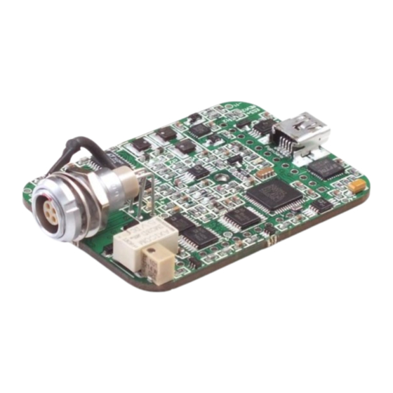
Getting started with the EmStat3+ module for OEM 2 Printed Circuit Board Layout EmSta3+ PCB layout The board has two pin headers: CON1 and CON2 CON1 is used to connect for instance the MUX multiplexer or any other peripheral. CON2 is used when serial TTL communications is used and provides also an external analog input and analog output line, with a range of 0 - 4.095 V. -
Page 6: Con2 Description
Getting started with the EmStat3+ module for OEM 2.2 CON2 description Function Tx (serial port) Rx (serial port) Reserved (DO NOT CONNECT THIS PIN) Voltage reference (4.096 V) Reserved for use with external interrupt signal DGND Reset (active high) Download (active low) ADC ch.2 (range 0 –... -
Page 7: Pinout Of Sensor Plug
Getting started with the EmStat3+ module for OEM 2.4 Pinout of sensor plug See CON4 on page 2. Front view of socket Solder side of socket 1 ● ● 4 4 ● ● 1 2 ● ● 3 3 ● ●... -
Page 8: Firmware
Press ‘Connect’ Load firmware file ESx##, where x is the EmStat type and ## the firmware version. Make sure the checkbox ‘PalmSens or EmStat is on, but does not work property' is checked Click button 'Update Firmware'. Remove the power supply briefly to force a reset Wait until updating has finished. -
Page 9: Instrumental Specifications
Getting started with the EmStat3+ module for OEM 4 Instrumental specifications Specifications of the EmStat3+ module: - dc-potential range ± 4.000 V - compliance voltage ± 8 V - applied dc-potential resolution 0.125 mV - dc-offset error 3 mV - accuracy ≤... -
Page 10: Appendix A: Change Emstat Usb Connection To Virtual Com Port
Getting started with the EmStat3+ module for OEM Appendix A: Change EmStat USB connection to virtual COM port 1. Connect EmStat to the USB port. 2. Open FT_PROG (see http://www.ftdichip.com/Support/Utilities.htm) 3. Click the “Scan and Parse” button 4. Change the Custom VID/PID to FTDI Default: Select FTDI Default 5.
Need help?
Do you have a question about the EmStat3+ and is the answer not in the manual?
Questions and answers