
Related Manuals for PalmSens EmStat3-MUX8


Summary of Contents for PalmSens EmStat3-MUX8
- Page 1 EmStat3-MUX8 for OEM Connecting a MUX8 board to an EmStat3 Last revision: May 27, 2015 © 2015 PalmSens BV www.palmsens.com...
-
Page 2: Table Of Contents
EmStat3-MUX8 for OEM Contents EmStat3 PCB ........................... 3 Connecting EmStat board to MUX8 multiplexer ................3 CON1 description ........................4 CON2 description ........................4 Pinout of sensor connector (CON4): ..................4 CON1 to MUX8 ........................5 MUX8 PCB ............................5 Functional diagram ........................ -
Page 3: Emstat3 Pcb
EmStat3-MUX8 for OEM Important before you start unpacking Please read this quick start guide carefully before unpacking the boards from their antistatic bags or using the kit, as it contains important information on how to avoid damage to the PCB’s. -
Page 4: Con1 Description
EmStat3-MUX8 for OEM 2.1 CON1 description Function Output line 3 reserved for Mux16 or digital input line 0 Output line 2 reserved for Mux16/8 Output line 1 reserved for Mux16/8 and switch box Output line 0 reserved for Mux16/8 and switch box and stirrer: 0 -off 1 - on Output: 5 V digital (max. -
Page 5: Con1 To Mux8
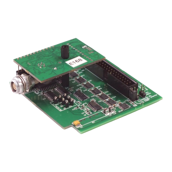
EmStat3-MUX8 for OEM 2.4 CON1 to MUX8 EmStat is to be connected to the MUX board using CON1. This can be done in two ways: Two ways of connecting the EmStat PCB to the MUX8 PCB 3 MUX8 PCB The MUX8 multiplexer is meant for use with 2- or 3- electrode sensors or cells up to 8 channels. -
Page 6: Set Standby Potential With The Vaux Pin
EmStat3-MUX8 for OEM 3.2 Set standby potential with the Vaux pin The Vaux pin can be used to set a standby potential on all unselected channels. Make sure the following jumpers are placed: Unselected WE to AGND: NOT PLACED Unselected WE to standby potential:... -
Page 7: Mux8 Configurations
J2: CE Direct If the sensor array has more than one working electrode, but one counter and/or reference electrode, this jumper is placed. CE from PalmSens is connected directly to pin 1 and pin 2 of CON1 J3: RE Direct If the sensor array has more than one working electrode, but one counter and/or reference, this jumper is placed. - Page 8 EmStat3-MUX8 for OEM Jumper settings for the available configurations: Conf. 1: Sensor array with up to eight working, eight reference and eight counter electrodes: Jumpers to be placed are: J4 and J5 The potential is only applied to the selected channel. All channels NOT selected are at open circuit.
-
Page 9: Electrode Connections
EmStat3-MUX8 for OEM 3.4 Electrode connections 3.5 Specifications Number of channels Multiplexer use: Sensor arrays with up to eight working, reference and counter electrodes Sensor arrays with up to eight working and eight combined reference/counter electrodes Sensor arrays with up to eight working electrodes all sharing the same reference and the same counter electrode ... -
Page 10: Pcb Dimensions
EmStat3-MUX8 for OEM 4 PCB dimensions 4.1 MUX8 PCB EmStat3-MUX8 for OEM... -
Page 11: Emstat Pcb
EmStat3-MUX8 for OEM 4.2 EmStat EmStat3-MUX8 for OEM... -
Page 12: Pcb's Connected - Option 1
EmStat3-MUX8 for OEM 4.3 PCB’s connected – option 1 variable (>18 if mini USB is used) EmStat3-MUX8 for OEM... -
Page 13: Pcb's Connected - Option 2
EmStat3-MUX8 for OEM 4.4 PCB’s connected – option 2 variable 101,30 EmStat3-MUX8 for OEM...
Need help?
Do you have a question about the EmStat3-MUX8 and is the answer not in the manual?
Questions and answers