Advertisement
Quick Links
Zero Emission Vehicles Australia
ZEVA MC600C / MC1000C
Motor Controller Assembly Manual
Written by Ian Hooper, October 2021
Introduction
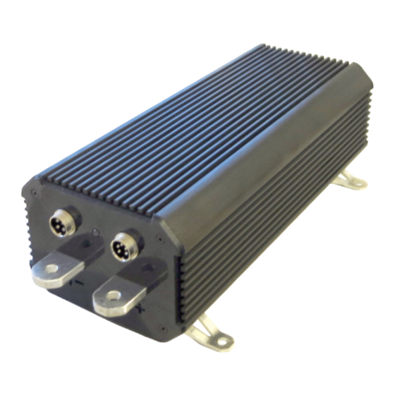
This document describes the assembly process for the ZEVA MC600C and MC1000C motor
controllers for Series DC and PMDC motors. It should also be useful for disassembling any
controllers that need repairs. Pictures shown are of an MC1000C. The MC600C is a similar
design, but with a shorter power stage (fewer components) - the differences should be intuitive
during assembly if you are making an MC600C.
Hopefully this manual will have sufficient detail for the assembly to go smoothly, but it is fairly
complicated so take your time, and it is best to read this entire manual before getting started so
you know what to expect.
1
Bill of Materials
This BoM covers parts needed for assembly, but not the individual components for each circuit
board used. For PCB assemblies, please refer to their individual BoMs provided. You will also
need the usual assortment of electronics tools such as soldering iron(s), pliers, side-cutters,
screwdrivers, multimeter, variable power supply, and preferably an oscilloscope for testing.
The motor controller has two microcontrollers that will need to be programmed using an
AVRISP type programmer (USBASP is a common and inexpensive option), and using software
such as AVR/Microchip Studio or AVR Dude to set the fuses (for clock speed etc) and
transferring the firmware. The main microcontroller can be programmed in-system after
assembly. The smaller microcontroller will need to be programmed before PCB assembly,
which can be set up using a SOIC8 to DIP8 adapter and some breadboard.
Description / Part Number
Logic board
Interface board
Capacitor boards (4oz copper essential)
Power boards (4oz copper essential)
Central heat block (162mm or 258mm long)
Thermal sheet, TG-A486S-320-320-0.23-0
M4x6 machine screws
IRFP4668 transistors
STTH6002 diodes
M3x12 countersunk machine screw
M3x35 machine screw
M3 Nyloc nut
Set of 3 busbars
Plastic tubing, 6mm OD, 4mm ID
M4x16 socket head machine screw
M4 spring washer
M4 nut
Thermistor (Altronics R4112)
M3x6 machine screw
M3 spring washer
5mm RGB LED
4-pin plug + socket (Altronics P0950, P0955)
5-pin plug + socket (Altronics P0951, P0956)
Hookup wire, ~AWG24, assorted colours
5mm RGB LED (common cathode)
M6x20 bolts (countersunk, if using ZEVA housing)
Motor Controller Assembly Manual
MC600C
MC1000C
1
1
1
1
5
8
5
8
1
1
1
1
10
16
10
16
10
16
2
2
10
16
12
18
1
1
60mm+
100mm+
30
48
30
48
30
48
1
1
1
1
1
1
1
1
1
1
1
1
0.5m
0.5m
1
1
2
3
2
Advertisement

Related Manuals for Zeva MC600C


Summary of Contents for Zeva MC600C
- Page 1 Series DC and PMDC motors. It should also be useful for disassembling any M3x6 machine screw controllers that need repairs. Pictures shown are of an MC1000C. The MC600C is a similar design, but with a shorter power stage (fewer components) - the differences should be intuitive M3 spring washer during assembly if you are making an MC600C.
- Page 2 PCB. Power stage The power stage uses a number of modular PCBs, 5x for the MC600C and 8x for the MC1000C. The small SOD123 diodes should be omitted (design change), and don’t fit the Interface board power transistors or diodes yet.
- Page 3 Zero Emission Vehicles Australia Motor Controller Assembly Manual • Cut two strips of thermal sheet, 160x20mm for MC600C or 256x20mm for MC1000C, and • Fasten the transistors and diodes to the heat block using M3x35 screws and nyloc nuts. Hold...
- Page 4 • Insert M4x16 socket head machine screws through all the holes in the capacitor boards (30 screws for MC600C, 48 screws for MC1000C). Fasten the middle row tightly into the heat block - about as tight as you can comfortably go using a screwdriver, or something like 1Nm.
- Page 5 Zero Emission Vehicles Australia Motor Controller Assembly Manual • The thermistor (temperature sensor) comes with short fly leads which need to be extended by about 20mm - something like the picture below. • Add a little thermal paste to the thermistor’s eyelet then it fasten to the heat block in horizontal orientation using an M3x6 machine screw with M3 washer under the screw head.
- Page 6 2 or 3 M6x20 countersunk machine screws. If using an original ZEVA extruded housing, the end plates attach to the housing using 4x M3x10 countersunk machine screws each.