Advertisement
Z
e
e r o
m i s s i o n
V
A
e h i c l e s
u s t r A l i A
http://www.zeva.com.au
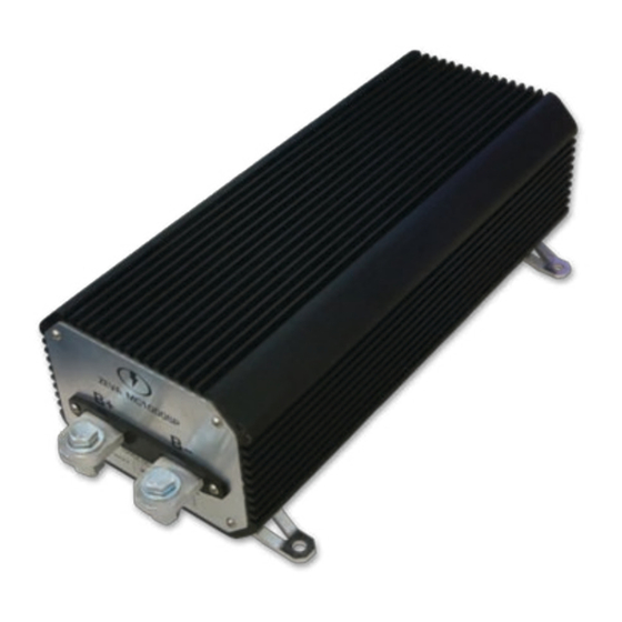
MC1000SP
150VDC 1000A motor controller
for Series DC and PM DC motors
Table of ConTenTS
1) Introduction
2) Safety Warning
3) Tech Support and Warranty Information
page
1
1
1
2
3
4
6
8
10
InTroduCTIon
Congratulations on your purchase of a ZEVA MC1000SP motor controller.
The MC1000SP represents the culmination of many years development, utilising the latest in power
semiconductors to create one of the most efficient EV motor controllers available - over 99% at
all times. Also featuring dual microprocessors for redundant safety, an advanced throttle algorithm
for the smoothest driving experience, silent operation at all times, a compact weather-resistant air-
cooled housing, and configurable operating parameters via simple serial connection.
We hope it provides you years of reliable service.
SafeTy WarnIng
Electric vehicle motor controllers are high powered devices which involve potentially lethal
voltages and currents. Proper precautions and electrical safety procedures should always be
observed, voltages above 110VDC should be considered dangerous, and vehicles should never
be worked on while main contactor(s) are engaged. Please read this manual carefully before using
the controller to ensure correct installation and operation. If you are unsure of anything, please
contact us before proceeding.
We have endeavoured to make a safe and reliable product which performs as described, however
since ZEVA has no control over the integration of its products into a vehicle, we can assume no
responsibility for the safety or functionality of the completed vehicle.
It is up to the end user to determine the suitability of the products for the purpose employed, and
the end user assumes all risks associated. Products should only be installed by suitably qualified
and experienced persons, and should always be used in a safe and lawful manner.
TeCh SuPPorT and WarranTy InforMaTIon
The MC1000SP motor controller is covered by a 12 month warranty against manufacturing faults
or failures under normal operating conditions. The warranty does not cover misuse of the product,
including but not limited to: excessive voltage or reversed polarity on input terminals, short
circuits on output terminals, excessive voltages applied to control wiring, opening of housing and/
or modification of internals, severe impact damage (e.g due to vehicle crashes), submersion in
water.
We have taken great care to design a safe and reliable product, but faults can happen. If you
believe your motor controller has a fault, please contact us via our website to discuss. If it is
determined that a hardware fault is the likely cause, we will provide an RMA number and return
address to proceed with repairs.
If you have any questions not covered by this manual, please contact us via our website:
http://www.zeva.com.au/Contact
1
Advertisement
Table of Contents

Related Manuals for Zeva MC1000SP


Summary of Contents for Zeva MC1000SP
-
Page 1: Table Of Contents
If you are unsure of anything, please contact us before proceeding. We have endeavoured to make a safe and reliable product which performs as described, however since ZEVA has no control over the integration of its products into a vehicle, we can assume no MC1000SP responsibility for the safety or functionality of the completed vehicle. It is up to the end user to determine the suitability of the products for the purpose employed, and the end user assumes all risks associated. Products should only be installed by suitably qualified 150VDC 1000A motor controller and experienced persons, and should always be used in a safe and lawful manner. -
Page 2: Features And Specifications
Caution: Since these threaded holes penetrate the housing, ensure that bolts do • Dimensions: 310x130x95mm housing only, 365x156x106mm inc terminals and brackets not extend more than 20mm into the case or they may damage components inside! • Weight: 4.5kg PaCkage ConTenTS: • 1x MC1000SP motor controller • 1x USB-Serial programming cable • 4x M8x25 bolts, washers, and nuts • 1x RGB LED for remote status light •... -
Page 3: Power Wiring
The power terminals are supplied cleaned and with a thin layer of Noalox contact paste applied to prevent re-oxidation. This paste should be left on the terminals when are attaching power cables. (The force of tightening the bolts will push the grease out and seal the contact area.) basic power wiring diagram for MC1000SP controller • The power cables in electric vehicles carry a large amount of power, and can emit a lot of electromagnetic interference (EMI) depending on their physical layout. To minimise EMI, it is best to keep the positive and negative cables close together – both the power cables from battery... -
Page 4: Control Wiring
• Type 3, hall effect Pedal assembly (hePa): HEPA pedals are becoming the industry standard rear shell, which then comes away with a small counterclockwise twist. for throttle devices in vehicles as they offer high reliability and safety through the use of dual Feed wires through the back of the rear shell before attaching to the pins to ensure the case can (redundant) hall effect sensors. A variety of different HEPA pedals are available, typically having go together again after wires are attached. For reliable connections, be sure to “tin” (add solder to) 6 wires for two independent 3-wire hall effect type throttles. The MC1000SP was designed to both the wires and the contacts before soldering them together. work with those providing dual analog outputs of around 0.7V–3.5V and 1.4V–4.2V. Use the The shell also has a cable stress relief clamp at the rear which can be fastened down to hold the Gnd and 5V pins on Plug 2 to provide power to both sensors. The 0.7-3.5V signal connects to cables. If your cables are too small for the clamp to engage, you can wrap some insulation tape Throttle A and the 1.4V-4.2V signal to Throttle B. With a HEPA throttle, the controller can detect around them to increase the diameter and ensure the clamp is able to hold them in place. a throttle fault if any four of the wires are disconnected, or if either of the throttle sensors are... -
Page 5: Operation
Controller on (No errors) Thermal cutback Controller temperature above 60˚C. Power reduces 12v logIC SuPPly slowly towards thermal shutdown threshold. The MC1000SP has an internal regulated power supply on its 12V input which allows it to operate Thermal shutdown Controller temperature above 90˚C. Thermal safely and correctly over an input voltage range of 8-18VDC. As a safety precaution, the controller shutdown until temperature reduces. will shut down if it detects the control voltage input dip below 8V. Battery voltage low Voltage at power terminals below minimum setting. -
Page 6: Customising Your Settings
Throttle ramp rate: This varies the rate at which the throttle is allowed to ramp up. A setting of zero gives instant throttle response, with numbers 1–4 giving increasingly gentle throttle ramps. • Throttle type: The MC1000SP supports three throttle types: (1) Three wire 0-5V analog plus Enable (2) Two wire 0-5KΩ plus enable and (3) Hall Effect Pedal Assembly (HEPA). Please refer to the Control Wiring: Throttle Device section for further details. hyperterminal settings windows •...
Need help?
Do you have a question about the MC1000SP and is the answer not in the manual?
Questions and answers