Table of Contents
Advertisement
Quick Links
Z
e
e r o
m i s s i o n
V
A
e h i c l e s
u s t r A l i A
http://www.zeva.com.au
EVMS Lite
Introduction
Thank you for purchasing ZEVA's Electric Vehicle Management System. The EVMS was
developed to address the need for safer, more reliable and better integrated EV conversions.
The Lite module is a simplified version of our EVMS Core, for those with simpler functional
requirements, and some features more suited to stationary and off-grid power applications.
The Lite communicates with battery management modules over CAN bus and manages drive/
load and charge circuits according to battery status, automatically shutting down outputs if
any cells exceed safe voltage range.
It also features auxiliary contactor control (for managing any mid-pack contactors), remote
LED for viewing status from the cabin and a buzzer output for audible warnings of any
errors. The EVMS Lite can optionally be used with an EVMS Monitor module for viewing
current vehicle status as well as full BMS information such as individual cell voltages and
pack statistics. The Monitor may also be used for reprogramming BMS parameters over the
CAN bus.
This manual describes the installation and operation of the EVMS Lite, with some additional
content describing interaction with the EVMS Monitor.
v2.0
Safety Warning
Electric vehicles are high powered devices which involve potentially lethal voltages and
currents. Proper precautions and electrical safety procedures should always be observed,
voltages above 110VDC should be considered dangerous, and vehicles should never be
worked on while power contactor(s) are engaged. Please read this manual carefully to
ensure correct installation and operation. If you are unsure of anything, please contact us
before proceeding.
We have endeavoured to make a safe and reliable product which performs as described,
however since ZEVA has no control over the integration of its products into a vehicle, we can
assume no responsibility for the final safety or functionality of the completed vehicle.
It is up to the end user to determine the suitability of the products for the purpose employed,
and the end user assumes all risks associated. Products should only be installed by suitably
qualified and experienced persons, and should always be used in a safe and lawful
manner.
Specifications
•
Power supply: 12-14V nominal (8-20V maximum)
•
Current consumption: 5mA idle, 25mA active
•
Contactor outputs rated at up to 5A
•
Dual CAN bus ports (5-pin Molex KK)
•
Optional shunt interface (100A/200A/500A 75mV)
•
Dimensions: 104x62x12mm
•
Weight: 50g
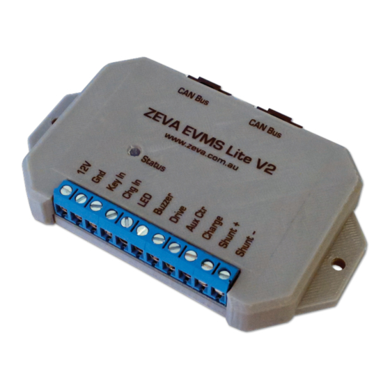
EVMS Lite Installation
The EVMS Lite should be mounted securely in the vehicle with screws through the holes in
the case, preferably in a location protected from the weather. The Lite has 11 screw terminals
for its main connections, plus two CAN ports the opposite side. Wire gauge for most I/O
connections should be around 18-20AWG to ensure reasonable mechanical strength and
current rating.
The following page shows a typical wiring diagram for an EVMS Lite in a vehicle (plus
associated BMS modules and EVMS Monitor).
Advertisement
Table of Contents

Related Manuals for Zeva EVMS Lite


Summary of Contents for Zeva EVMS Lite
- Page 1 We have endeavoured to make a safe and reliable product which performs as described, however since ZEVA has no control over the integration of its products into a vehicle, we can assume no responsibility for the final safety or functionality of the completed vehicle.
- Page 2 The diagram below shows typical wiring for an EVMS Lite installation. Note that the diagram does not show a main fuse (5A recommended) and inertia switch (crash sensor), which should both be installed between the 12V battery and the EVMS Lite’s 12V supply. The LED output supplies up to 5mA for powering a remote status LED, and Buzzer outputs 12V whenever an error is present – both...
- Page 3 Current Shunt cabin. 5mA limited. Connect this pin to LED anode, and The EVMS Lite optionally uses a current shunt to measure current flow in the traction circuit, cathode to ground/chassis. which allows it to calculate battery state-of-charge. The shunt measurement electronics are...
- Page 4 EVMS: Id l e V ol tage The default display when the vehicle is idle (neither – driving nor charging), for systems with a current shunt If the EVMS detects an error, this warning page Wa rn ing: C ur rent and hence able to calculate State of Charge, Current will be displayed.
- Page 5 BMS module should expect. EVMS automatically shuts the system down. In Running mode, only a warning is provided and the user must decide the appropriate action. List of settings - EVMS Lite Stationary Mode YES/NO Switches the EVMS into Stationary Mode, for battery backup and off-grid power type The following table describes the parameters available in the General Settings page.
- Page 6 BMS - overtemp A BMS module has reported a temperature above the Monitor device. To remedy this, simply turn the key on and off, or turn the EVMS Lite off and programmed threshold. on again, then enter Setup as normal within 1 minute.
Need help?
Do you have a question about the EVMS Lite and is the answer not in the manual?
Questions and answers