Table of Contents
Advertisement
Quick Links
Advertisement
Table of Contents

Subscribe to Our Youtube Channel
Related Manuals for Hoffman JEL Series


Summary of Contents for Hoffman JEL Series
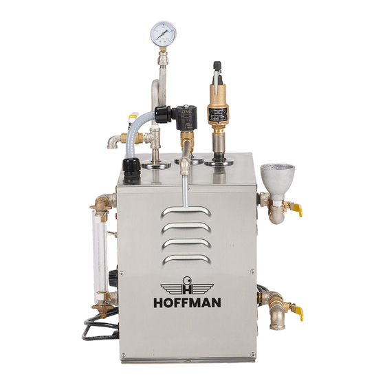
- Page 1 JEL3 INSTRUCTION MANUAL & PARTS LIST ELG Series 2-GALLON STEAM GENERATORS For original quality parts call: 1-800-221-0146 or fax: 1-570-928-9807 www.buyhoffmansteamnow.com www.buyhoffmansteamnow.com 2023 UnityLab Corp. All rights reserved. ©/TM 2023 UnityLab Corp. All rights reserved. ©/TM...
-
Page 2: Table Of Contents
5.4 REPLACING THE GAUGE SIGHT GLASS ................11 5.5 REPLACING THE HEATING ELEMENT Hoffman also offers a wide variety of options for the steam generators. For a listing of the options available, please contact your Hoffman Distributor. 5.6 REPLACING THE LOW WATER SWITCH ................12 5.7 REPLACING THE ELECTRIC FOOT SWITCH AND/OR CORD ........ -
Page 3: Preliminary Delivery Inspection
SOME PROBABILITY OF DEATH OR SERIOUS PERSONAL INJURY. BEING SERVICED OR MAINTAINED. 1.5.2 SAFETY FEATURES WARNING The following are safety features, which are incorporated into the Steam WHEN SERVICING THIS MACHINE, USE ONLY APPROVED HOFFMAN Generator: REPLACEMENT PARTS. ASME Pressure Vessel. 2. ASME Pressure Relief Valve. -
Page 4: Installation
ALWAYS PROPERLY GROUND THE UNIT BEFORE OPERATING. ONLY A LICENSED B. Pressure Switch Controlled Units are factory set and do not require ELECTRICIAN SHOULD SERVICE OR INSTALL A HOFFMAN GENERATOR. adjustment. 6. For Models with a Low Water Cutoff with Manual Reset: Once the power is turned on and the boiler is filled with water, push the reset switch. -
Page 5: Maintenance
JEL3 TECHNICAL MANUAL 5.0 TROUBLESHOOTING & SERVICING 4.0 MAINTENANCE The Hoffman Electric Steam Generator is compact, easy to clean and easy to 5.1 TROUBLESHOOTING TABLE maintain. It is strongly suggested that the following steps be followed to ensure a long and trouble free life for the boiler. -
Page 6: Adjusting The Steam Pressure
JEL3 TECHNICAL MANUAL 5.2 ADJUSTING THE STEAM PRESSURE PROBLEM POSSIBLE CAUSE CORRECTIVE ACTION 5.2.1 THERMOSTAT CONTROL See Section 4.3 – Blowing Down the Power the boiler. Boiler. Rust is a normal occurrence in steam generator shells. The rust 2. Turn the thermostat to “10.” appearance in the water will slowly Water is dark 3. -
Page 7: Replacing The Gauge Sight Glass
JEL3 TECHNICAL MANUAL 5.4 REPLACING THE GAUGE SIGHT GLASS Fill the boiler to the normal level, and CHECK FOR ANY LEAKS. Turn off power to the boiler by pulling the plug or turning off power at the 12. Power the boiler and allow the boiler to come up to pressure. CHECK FOR ANY branch switch or the circuit breaker. -
Page 8: Replacing The On/Off Switch
JEL3 TECHNICAL MANUAL 5.9 CLEANING THE ELECTRIC SOLENOID VALVE 5. Disconnect the cord wires from the foot switch. (To be performed by a licensed plumber) 6. Check continuity through the switch while holding the switch lever down. If For Models: JEL-3, JEL-4, JEL-6 the switch passes the test, skip to number 10. -
Page 9: Tables
JEL3 TECHNICAL MANUAL 6.0 TABLES Table 6.2.1 MODEL VOLTAGE PHASE AMPS 6.1 PRESSURE VS. TEMPERATURE NUMBER The following table shows the relationship between steam pressure in pounds JEL-1 per square inch (psig), and temperature in degrees Fahrenheit (ºF). This table JEL-2 can be useful in determining the steam temperature at a corresponding JEL-3... - Page 10 JEL3 TECHNICAL MANUAL Figure 7.1 – Assembly for Models: JEL-1, JEL-2, JEL-3, JEL-4, JEL-6, ELG-4, ELG- Figure 7.2 – 52488 (rev C) Wiring Diagram for Models: JEL-1, JEL-2, JEL-3, JEL-4, 4.2, ELG-5, ELG-5.2, ELG-6, ELG-7 JEL-6, ELG-4, ELG-4.2, ELG-5, ELG-5.2, ELG-6, ELG-7 Optional Parts List Part No.
Need help?
Do you have a question about the JEL Series and is the answer not in the manual?
Questions and answers