Thermo King Smart Reefer 2, SR-2 - Microprocessor Driver Manual
- Driver manual (2 pages) ,
- Driver manual (2 pages)
Advertisement
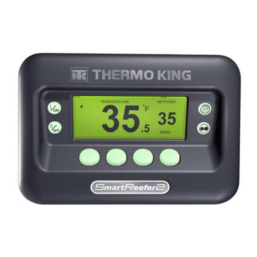
Simple to Start
- Press the ON Key.

- A series of start-up screens will appear.
- The Standard Display appears showing setpoint and box temperature when the unit is running.
- The Standard Display defaults to the "Temperature Watch" screen after 2 1/2 minutes. This screen displays same setpoint and box temperature in larger font.


NOTE: For more detailed information, see the Operation chapter in the appropriate unit operating manual.
Simple to Set
CYCLE-SENTRY or Continuous Run
- Return to the Standard Display.

- Press the MODE SELECTION Key.
- The "Programming Continuous Mode" or "Programming CYCLE- SENTRY Mode" screen briefly appears.
- The "New System Mode is Continuous" screen or the "New System Mode CYCLE- SENTRY" screen briefly appears.
- The Standard Display appears and the heading on top of screen reads the new mode.

- Pressing the MODE SELECTION Key again will change the unit back to the previous mode.


NOTE: For more detailed information, see the Operation chapter in the appropriate unit operating manual.
Setpoint Temperature
- Return to the Standard Display.

- Press the SETPOINT Key on the Standard Display.
- Press the + or - Keys to change the setpoint reading.

- Press the YES or NO key accordingly.

- The Standard Display appears with setpoint changed to the new setpoint.


NOTE: For more detailed information, see the Operation chapter in the appropriate unit operating manual.
Simple to Check
Gauges
- Return to the Standard Display.

- Press the GAUGES Key.
- Press BACK or NEXT Keys to scroll through following gauges: Coolant Temperature, Coolant Level, Engine Oil, Pressure, Amps, Battery Voltage, Engine RPM, Discharge Pressure, Suction Pressure, ETV Position, I/O. If no keys are pressed within 30 seconds, the screen will return to the Standard Display.

- Press the LOCK Key to display any gauge screen for an indefinite period. Press the key again to unlock the screen.
- Press the EXIT Key to return to the Standard Display.


NOTE: For more detailed information, see the Operation chapter in the appropriate unit operating manual.
Pretrip Test
- Clear all alarm codes.
- Return to the Standard Display.

- Press the MENU key.
- Press the NEXT Key as required to show the Pretrip Menu.

- Press the SELECT Key to start a Pretrip Test.
- If the unit is not running, a Full Pretrip will be initiated. If the unit is running in either diesel or electric mode, a Running Pretrip will be performed.
- When all tests are complete, the results are reported as PASS, CHECK or FAIL. If the results are CHECK or FAIL, the accompanying alarm codes will direct the technician to the cause of the problem.


NOTE: For more detailed information, see the Operation chapter in the appropriate unit operating manual.
Hourmeters
- Return to the Standard Display screen.

- Press the MENU Key.
- Scroll through Main Menu by repeatedly pressing the NEXT and BACK Keys until the hourmeters Main Menu Screen appears.

- Press the SELECT Key to enter the Hourmeters Menu.
- Press the NEXT and BACK Keys to view the Hourmeter Displays.


NOTE: For more detailed information, see the Operation chapter in the appropriate unit operating manual.
Simple to Defrost
Initiate Manual Defrost
- Return to the Standard Display.

- Press the DEFROST Key.
- Miscellaneous defrost programming screens appear.

- A modified Standard Display screen appears. The bar indicator will fill in showing the time remaining to complete the Defrost cycle. When the Defrost cycle is complete the display returns to Standard Display screen.


NOTE: For more detailed information, see the Operation chapter in the appropriate unit operating manual.
Simple to Access
Sensors
- Return to the Standard Display.

- Press the SENSORS Key.
- Press the BACK or NEXT Keys to scroll through the following sensor screens: Control Return Air Temperature, Display Return Air Temperature, Control Discharge Air Temperature, Display Discharge Air Temperature, Temperature Differential, Evaporator Coil Temperature, Ambient Air Temperature, Spare 1 Temperature, Datalogger Temperature Sensors 1-6 and the Board Temperature Sensor. If no keys are pressed within 30 seconds, the screen will return to the Standard Display.

- Press the LOCK Key to display any sensor screen for an indefinite period. Press the key again to unlock the screen.
- Press the EXIT Key to return to the Standard Display.


NOTE: For more detailed information, see the Operation chapter in the appropriate unit operating manual.
Simple to View
Cause of Alarm
- Return to the Standard Display Screen.

- Press the MENU Key.
- Press the NEXT Key until the Alarm Menu appears.

- Press the SELECT Key. The Alarm Display will appear
- If no alarms are present, Alarm 00 is shown.

- Press the EXIT Key to return to the Standard Display.
- If alarms are present, the quantity of alarms and the most recent alarm code number will be shown.

- If there is more than one alarm, press the NEXT Key to view each alarm.
- If a serious alarm occurs, the unit will be shut down to prevent damage to the unit or the load. If this occurs, the display will show that the unit is shut down and display the alarm code that caused the shutdown.


NOTE: For more detailed information, see the Operation chapter in the appropriate unit operating manual.
Clearing Alarm Codes
- Press the CLEAR Key to clear an alarm.

- The display screen will return to the Standard Display when the alarms are cleared.

- Press the HELP key for additional information regarding the alarm shown on the display. Also see the complete Alarm Code list in the next column.


NOTE: For more detailed information, see the Operation chapter in the appropriate unit operating manual.
Simple to Determine
Cause of Alarm
- No Alarms Exist
- Evaporator Coil Sensor
- Control Return Air Sensor
- Control Discharge Air Sensor
- Ambient Air Sensor
- Coolant Temperature Sensor
- Engine RPM Sensor
- High Evaporator Temperature
- High Discharge Pressure
- Unit Controlling on Alternate Sensor
- Sensor Shutdown
- Sensor Check
- Glow Plug Check/Intake Air Heater
- Engine Failed to Crank
- High Engine Coolant Temperature
- Low Engine Oil Pressure
- Engine Failed to Start
- Cooling Cycle Check
- Heating Cycle Check
- Cooling Cycle Fault
- Heating Cycle Fault
- Alternator Check
- Refrigeration Capacity Check
- Motor RPM High
- Pre-Trip Abort
- Defrost Damper Circuit
- Defrost Damper Stuck Closed
- Oil Pressure Switch
- Refrigeration Capacity Low
- Check Engine RPM
- Run Relay Circuit
- Electric Motor Failed to Run
- Engine Coolant Level
- Electric Phase Reversed
- Water Valve Circuit
- High Speed Circuit
- Check Engine Coolant Temperature
- Unit Forced to Low Speed
- Unit Forced to Low Speed Modulation
- Check Fuel System
- Hot Gas Bypass or Hot Gas Bypass Circuit
- Check Air Flow
- Check Belts or Clutch
- Reset Clock
- Heat Circuit
- Economizer Valve Circuit
- Test Mode Time-Out
- Check Engine Speeds
- Low Battery Voltage Check
- Ammeter Out of Calibration Range
- Engine Stopped - Reason Unknown
- Pretrip Reminder
- Low Engine Oil Level
- Liquid Line Solenoid
- Hourmeters Failure
- Maintenance Hourmeter 4 Exceeds Set Time Limit
- Maintenance Hourmeter 5 Exceeds Set Time Limit
- Maintenance Hourmeter 6 Exceeds Set Time Limit
- Controller Reset to Defaults
- Internal Fault Codes
- Internal Fault Codes
- Internal Fault Codes
- Internal Fault Codes
- Data Log Overflow
- Compressor Temperature Sensor
- High Compressor Temperature
- High Compressor Temperature Shutdown
- Low Coolant Temperature
- Restart Null
- Forced Unit Operation
- Discharge Pressure Sensor
- Suction Pressure Transducer
- Electronic Throttling Valve Circuit
- Electric Overload
- Electric Ready Input
- Sensor Grades Not Set
- Low Compressor Suction
- Loader #1
- Loader #2
- Low Fuel Level
- Fuel Level Sensor
- High Compressor Pressure Ratio
- Door Open Time-Out
- High Discharge Pressure
- Unit Configuration
- Auto Switch to Electric
- Auto Switch to Diesel
- Liquid Injection Circuit
- Diesel/Electric Relay Circuit
- Setpoint Not Entered
- Engine Run Time Maintenance Reminder #1
- Engine Run Time Maintenance Reminder #2
- Electric Run Time Maintenance Reminder #1
- Electric Run Time Maintenance Reminder #2
- Total Unit Run Time Maintenance Reminder #1
- Total Unit Run Time Maintenance Reminder #2
- Power On Hours
- Spare DIgital Inputs
- Spare Digital Outputs
- Display Return Air Sensor
- Display Discharge Air Sensor
©Thermo King Corporation

Documents / ResourcesDownload manual
Here you can download full pdf version of manual, it may contain additional safety instructions, warranty information, FCC rules, etc.
Download Thermo King Smart Reefer 2, SR-2 - Microprocessor Driver Manual
Advertisement


Need help?
Do you have a question about the Smart Reefer 2 and is the answer not in the manual?
Questions and answers