Table of Contents
Advertisement
Quick Links
Safety • Set-Up • Operation • Adjustments • Maintenance • Troubleshooting • Warranty
OPERATOR'S MANUAL
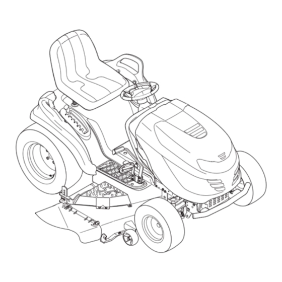
Hydrostatic Garden Tractor — Model 81GK
IMPORTANT:
READ SAFETY RULES AND INSTRUCTIONS
CAREFULLY BEFORE OPERATING EQUIPMENT.
769-04817
P. O. Box 1386, KITCHENER, ONT. N2G 4J1
PRINTED IN U.S.A.
1/28/09
Advertisement
Table of Contents

Subscribe to Our Youtube Channel
Related Manuals for White Outdoor 81GK


Summary of Contents for White Outdoor 81GK
- Page 1 Safety • Set-Up • Operation • Adjustments • Maintenance • Troubleshooting • Warranty OPERATOR’S MANUAL Hydrostatic Garden Tractor — Model 81GK IMPORTANT: READ SAFETY RULES AND INSTRUCTIONS CAREFULLY BEFORE OPERATING EQUIPMENT. 769-04817 P. O. Box 1386, KITCHENER, ONT. N2G 4J1 PRINTED IN U.S.A.
-
Page 2: Table Of Contents
This information will be necessary to use the manufacturer’s web site and/or help from the Customer Support Department or an WHITE OUTDOOR CANADA authorized service dealer. KITCHENER, ON N2G 4J1 Customer Support Please do NOT return the unit to the retailer from which it was purchased, without first contacting Customer Support. -
Page 3: Slope Gauge
Use this page as a guide to determine slopes where you may not operate safely. Do not operate your lawn mower on such slopes. Slope Gauge WARNING Do not mow on inclines with a slope in excess of 15 degrees (a rise of approximately 2-1/2 feet every 10 feet). -
Page 4: Safe Operation Practices
WARNING: Engine Exhaust, some of its constituents, and certain vehicle components contain or emit chemicals known to State of California to cause cancer and birth defects or other reproductive harm. DANGER: This machine was built to be operated according to the rules for safe operation in this manual. As with any type of power equipment, carelessness or error on the part of the operator can result in serious injury. - Page 5 Slope Operation a. Keep children out of the mowing area and in watchful care of a responsible adult other than the operator. Slopes are a major factor related to loss of control and tip-over b. Be alert and turn machine off if a child enters the area. accidents which can result in severe injury or death.
- Page 6 e. Extinguish all cigarettes, cigars, pipes and other frequently check components and replace immediately with sources of ignition. original equipment manufacturer’s (O.E.M.) parts only, listed in this manual. “Use of parts which do not meet the original f. Never fuel machine indoors. equipment specifications may lead to improper performance g.
- Page 7 This page depicts and describes safety symbols that may appear on this product. Read, understand, and follow all instructions on the machine before attempting to assemble and operate. Symbol Description Safe READ THE OPERATOR’S MANUAL(S) Read, understand, and follow all instructions in the manual(s) before attempting Symbols to assemble and operate DANGER—...
-
Page 8: Setting Up Your Lawn Tractor
Connecting the Battery Cables CAUTION: When attaching battery cables, always connect the POSITIVE (Red) wire to its terminal first, followed by the NEGATIVE (Black) wire. Setting Up For shipping reasons, both battery cables on your equip- ment may have been left disconnected from the terminals Your Lawn at the factory. - Page 9 Shipping Brace Removal WARNING: Make sure the riding mower’s engine is off, remove the ignition key, and set the parking Setting Up brake before removing the ship- ping brace. Your Lawn • Locate the shipping brace, if present, and accompany- Tractor ing warning tag found on the right side of the mower, between the discharge chute and the cutting deck.
- Page 10 Attaching The Seat NOTE: For shipping reasons, the seat is either fastened to the tractor seat’s pivot bracket with a plastic tie, or mounted backward to the pivot bracket. In either case, free the seat from its shipping position being careful not to Setting Up bend or kink the wiring harness and follow the instruc- tions below to attach it.
- Page 11 Setting the Deck Gauge Wheels and Roller Move the tractor on a firm and level surface, preferably pavement, and proceed as follows • Select the height position of the cutting deck by plac- Setting Up ing the deck lift lever in the normally desired mowing height setting (any of the six different cutting height Your Lawn notches on the right fender).
-
Page 12: Operating Your Lawn Tractor
Know Your Lawn Tractor Throttle Control Operating Ignition Switch Module Your Lawn Tractor PTO (Blade Engage) Knob Brake Pedal Systems Indicator Monitor Drive Pedal Cruise Choke Control Parking Brake Control Button Seat NOTE: Any reference Adjustment Lever in this manual to Deck Lift the RIGHT or LEFT Lever... - Page 13 Choke Control IMPORTANT: Prior to operating the tractor, refer to both Safety Interlock Switches and Starting The Engine On some models, moving the in this section of the manual for detailed instructions throttle lever all the way forward regarding the Ignition Switch Module and operating the activates the engine’s choke tractor in REVERSE CAUTION MODE.
- Page 14 Electric PTO (Blade Engage) Knob The Indicator Monitor will also remind the operator of maintenance intervals for changing the engine oil. The Equipped) LCD will alternately flash the recorded hours, “CHG” and To engage the power to the cutting deck or other (sepa- “OIL”...
- Page 15 Cruise Control Button • With the ignition key in the NORMAL MOWING position, the electric PTO (Blade Engage) clutch will The cruise control button is automatically shut off if the PTO (Blade Engage) knob located on the tractor dash is moved into the engaged (ON) position with the panel to the left of the ignition drive pedal in Reverse.
- Page 16 WARNING AVOID SERIOUS INJURY OR DEATH • GO UP AND DOWN SLOPES, NOT ACROSS. Operating • AVOID SUDDEN TURNS. • DO NOT OPERATE THE UNIT WHERE IT COULD SLIP OR TIP. Your Lawn • IF MACHINE STOPS GOING UPHILL, STOP BLADE(S) AND Tractor BACK DOWNHILL SLOWLY.
- Page 17 Driving The Tractor WARNING: Avoid sudden starts, excessive speed and sudden stops. WARNING: Do not leave the seat Operating of the tractor without first placing the PTO (Blade Engage) knob (or Your Lawn lever) in the disengaged (OFF) Tractor position, depressing the brake pedal and engaging the parking brake.
- Page 18 Setting The Cruise Control Engaging the Blades Engaging the PTO (Blade Engage) transfers power to the NOTE: The cruise control feature should only be utilized cutting deck or other (separately available) attachments. while traveling in the forward direction. To engage the blades, proceed as follows: •...
- Page 19 Mowing Headlights • On some models, the lamps are ON whenever the WARNING: To help avoid blade tractor’s engine is running. On other models, the contact or a thrown object lamps are ON whenever the ignition key is moved out injury, keep bystanders, helpers, of the STOP position.
-
Page 20: Adjusting Your Lawn Tractor
WARNING: Never attempt to make Leveling the Deck any adjustments while the engine NOTE: Check the tractor’s tire pressure before performing is running, except where specified any deck leveling adjustments. Refer to Tires on page 24 in the operator’s manual. for information regarding tire pressure. - Page 21 Parking Brake Adjustment Steering Adjustment If the tractor turns tighter in one direction than the other, WARNING: Never attempt to adjust or if the ball joints are being replaced due to damage or the brakes while the engine is run- wear, the steering drag links may need to be adjusted.
-
Page 22: Maintaining Your Lawn Tractor
7. Refill the engine with new motor oil as instructed in the Engine Operator/Owner Manual packed with your unit. IMPORTANT: Refer to the Engine Operator/Owner Manual packed with your unit for information regarding the quantity and proper weight of motor oil. Maintaining Air Cleaner Service the pre-cleaner, if so equipped, and cartridge/air... - Page 23 Maintaining Your Lawn Tractor Figure 6-2 Figure 6-4 IMPORTANT: Make IMPORTANT: Make certain the tractor’s discharge chute certain the tractor’s is directed AWAY from your house, garage, parked cars, discharge chute is etc. directed AWAY from 2. Disengage the PTO (Blade Engage), move the shift your house, garage, lever into the neutral position, set the parking brake, parked cars, etc.
- Page 24 Tires 3. Remove the belt keeper rod from around the engine pulley by removing the self-tapping screw. WARNING: Never exceed the 4. Remove the deck belt from around the tractor’s maximum inflation pressure engine pulley (or electric PTO clutch, if so equipped). shown on the sidewall of tire.
- Page 25 1. Connect end of one jumper cable to the positive terminal of the good battery, then the other end to the positive terminal of the dead battery. 2. Connect the other jumper cable to the negative terminal of the good battery, then to the frame of the unit with the dead battery.
- Page 26 Fuses Idler Pulley • A fuse is installed in your tractor’s wiring harness to protect the tractor’s electrical system from damage Belt Guard caused by excessive amperage. • If the electrical system does not function, or your tractor’s engine will not crank, first check to be Maintaining certain that the fuse has not blown.
- Page 27 Maintaining Your Lawn Tractor Figure 6-11 This Operators Manual covers a range of product specifications for various models. Characteristics and features discussed and/or illustrated in this manual may not be applicable to all models. MTD LLC reserves the right to change product speci- fications, designs and equipment without...
-
Page 28: Off-Season Storage / Attachments
Clean and lubricate the tractor as instructed in the Follow the instructions in the separate engine manual MAINTAINENCE section of this manual before storing packed with your unit for proper engine care prior to for an extended period. storing your tractor. WARNING: Drain fuel only into WARNING: Never store the an approved container outdoors,... -
Page 29: Trouble Shooting
Cause Problem Remedy Engine fails to start 1. PTO engaged. 1. Place PTO knob (or lever) in disengaged (OFF) position. 2. Connect wire(s) to spark plug(s). 2. Spark plug wire(s) disconnected. 3. Fill tank with clean, fresh gasoline. 3. Fuel tank empty or stale fuel. Trouble 4. -
Page 30: Replacement Parts
Replacement Parts Hydrostratic Garden Tractor Drive Belt (Mowing Deck) 54” Deck 754-0642 Deck Blades (54” Deck) 742-0677B Deck Spindles 618-0671B Deck Wheel 5.0 x 1.38 (front) 734-04155 Battery 925-1707D Tire (Front) 16” x 7.5” x 8” Square Shoulder 734-04088A For parts and/or Tire (Rear) 22”... -
Page 31: Warranty
THREE YEAR LIMITED WARRANTY The limited warranty set forth below is given by MTD Products Limited with respect to new merchandise purchased and used in Canada and/or its territories and possessions (either entity respectively, “MTD”). MTD warrants this product (excluding its normal wear parts as described below) against defects in material and workmanship for a period of three (3) years commencing on the date of original purchase and will, at its option, repair or replace, free of charge, any part found to be defective in materials or workmanship. -
Page 32: Emissions Control Warranty Statement
CALIFORNIA EMISSION CONTROL WARRANTY STATEMENT YOUR WARRANTY RIGHTS AND OBLIGATIONS The California Air Resources Board and MTD Consumer Group Inc are pleased to explain the evaporative emission control system warranty on your 2008 lawn mower. In California, new lawn mowers must be designed, built and equipped to meet the State’s stringent anti-smog standards. MTD Consumer Group Inc must warrant the EECS on your lawn mower for the period of time listed below provided there has been no abuse, neglect or improper maintenance of your lawn mower. - Page 33 WARRANTED PARTS: The repair or replacement of any warranted part otherwise eligible for warranty coverage may be excluded from such warranty coverage if MTD Consumer Group Inc demonstrates that the lawn mower has been abused, neglected, or improperly maintained, and that such abuse, neglect, or improper maintenance was the direct cause of the need for repair or replacement of the part.
- Page 34 notes . . .
Need help?
Do you have a question about the 81GK and is the answer not in the manual?
Questions and answers