
Related Manuals for Silvercrest 66252


Summary of Contents for Silvercrest 66252
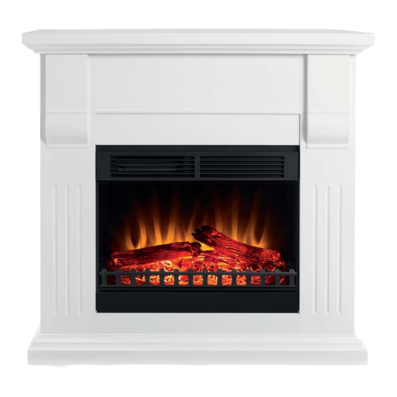
- Page 1 Electric Fireplace SEKU 2000 A1 Electric Fireplace Operating instructions KOMPERNASS GMBH BURGSTRASSE 21 · D-44867 BOCHUM www.kompernass.com ID-Nr.: SEKU 2000 A1-03/11-V3 IAN 66252...
-
Page 2: Table Of Contents
Contents Introduction ..... . 2 Assembly ......10 Information for these operating instructions . -
Page 3: Introduction
Introduction Introduction Information for these operating instructions These operating instructions are a component of the SEKU 2000 A1 Electric Fireplace (henceforth designated as the appliance) and they provide you with important information about the intended use, safety, installation and connection as well as operation of the appliance. These operating instructions must at all times be kept available close to the appliance. -
Page 4: Warnings
Introduction Warnings In these operating instructions the following warnings are used: DANGER A warning at this danger level indicates a threateningly dangerous situation. If the dangerous situation is not avoided, it could result in death or serious injury. Compliance with the instructions in this warning is necessary to avoid the risk of death or serious injury. ►... -
Page 5: Safety
Safety Safety In this chapter you are being given important safety information regarding the handling of the appliance. This appliance complies with the statutory safety regulations. Incorrect usage can, however, lead to personal and property damage. Do not cover the appliance! Covering the appliance can cause overheating and thus lead to the development of a fi... -
Page 6: Setting Up And Connecting
Setting up and connecting Protect the appliance from moisture and liquid penetration. ■ The appliance may not be used directly adjacent to a bath-tub, shower or swimming pool. ■ Always pull on the plug when disconnecting from the mains power socket, never pull on the connection cable. ■... -
Page 7: Installation Requirements
Setting up and connecting Installation requirements For the safe and correct operation of the appliance, the installation site must satisfy the following requirements: The appliance must be placed on a fi rm, fl at and horizontal surface. ■ Do not place the appliance in a hot, wet or very humid environment or close to infl ammable materials. ■... -
Page 8: Operating Components
Operating components Operating components NOTICE The operating elements are on the front of the appliance, above right and behind the ventilation grille. ► To operate them, fold the ventilation grille forward. ► ON/OFF switch (Flames) ON/OFF switch (Heating, level 1) ON/OFF switch (Heating, level 2) Temperature control (Thermostat) Dimmer (for fl... -
Page 9: Set Up
Set up Set up Before the appliance can be set up, the fi re surround must be assembled. NOTICE Check the contents to make sure everything is there and for visible damage. ► Firstly, become familiar with all parts involved in the assembly. ►... -
Page 10: Screws And Assembly Material
Set up Screws and assembly material No.: Designation: Number: Screws 6 x 25 mm Wood plugs Double locking pin Single locking pin Adapter sleeve Fixing device Connection blocks NOTICE You require a screwdriver for the assembly; this is not supplied. ►... -
Page 11: Assembly
Assembly Assembly Step 1 Screw 5 single locking pins with a screwdriver into the prepared holes on the left front panel ♦ Insert 5 adapter sleeves into the 5 large holes of the left side panel . Thereby, with the screwdriver ♦... - Page 12 Assembly Then, bring the front panel and side panel together at right angles, so that the locking pins ♦ enter the holes on the right edge of the side panel. When done, screw all 5 adapter sleeves to the right with the screwdriver until the locking pins are ♦...
- Page 13 Assembly Step 5 Place the fl oor plate on the fl oor. ♦ Insert the 4 connection blocks in the holes of the fl oor plate and secure them with 4 screws of type ♦ Now take the previously assembled unit and carefully place it on the fl oor plate as shown in the following ♦...
- Page 14 Assembly Step 7 Screw the 6 single locking pins with a screwdriver into the holes provided on the front and rear ♦ support frame plates. Place the 6 adapter sleeves in the large pre-drilled holes in the three middle support frame plates. ♦...
- Page 15 Assembly Installing the appliance in the fi re surround To fi nalise, install the appliance in the assembled fi re surround. Place the appliance carefully on the base plate (from the rear of the fi re surround) and then push it ♦...
-
Page 16: Handling And Operation
Handling and operation/Maintenance Handling and operation NOTICE See also "Operating Elements" on page 7. ► In this chapter you receive important information for the handling and operation of the appliance. Activate the ON/OFF switch to turn the unit on. The fl ame replication lights up. Programme in the ♦... -
Page 17: Cleaning
Maintenance/Cleaning/Troubleshooting Switch the appliance off . ♦ Pull the plug from the mains power socket. ♦ Loosen the four screws on the rear panel and remove the metal ventilation panel ♦ Carefully replace the defective bulb in the light shaft. ♦... -
Page 18: Malfunction Causes And Remedies
Troubleshooting/Storage/Disposal Malfunction causes and remedies The following table will help with localising and remedying minor malfunctions: Defect Possible cause Solution The appliance is not switched on. Switch the appliance on. Insert the plug into the The plug is not inserted. The fl... -
Page 19: Appendix
Appendix Appendix Technical data General Input voltage 220 - 240 Mains frequency Power consumption Heating level 1 1000 Heating level 2 2000 Bulb 2 x 25 2 x Bulbs E14 Ambient temperature +5 to +45 °C Humidity (no condensation) 5 to 90 Measurements (W x H x D): 100 x 100 x 39 Weight... -
Page 20: Warranty
Repairs carried out after expiry of the warranty period are subject to payment. Service Service Great Britain Tel.: 0871 5000 720 (£ 0.10/Min.) E-Mail: kompernass@lidl.gb IAN 66252 Service Ireland Tel.: 1890 930 034 (0,08 EUR/Min., (peak)) (0,06 EUR/Min., (off peak)) E-Mail: kompernass@lidl.ie...
Need help?
Do you have a question about the 66252 and is the answer not in the manual?
Questions and answers
Como encender solo la llama sin calefaccion
To turn on the flame only without heating on the Silvercrest model SEKU 2000 A1 (66252), press the power switch. The flame image will light up. Do not activate the heating switches (switch 2 and switch 3).
This answer is automatically generated