Table of Contents
Advertisement
Quick Links
Operator's Manual
Automatic Transmission
Garden Tractor Model 1212
IMPORTANT: READ SAFETY RULES AND INSTRUCTIONS CAREFULLY
Warning:
This unit is equipped with an internal combustion engine and should not be used on or near any unimproved forest-
covered, brush-covered or grass-covered land unless the engine's exhaust system is equipped with a spark arrester meeting
applicable local or state laws (if any). If a spark arrester is used, it should be maintained in effective working order by the operator.
In the State of California the above is required by law (Section 4442 of the California Public Resources Code). Other states may have
similar laws. Federal laws apply on federal lands. A spark arrester for the muffler is available through your Cub Cadet dealer or con-
tact the service department, P.O. Box 368023 Cleveland, Ohio 44136-9722.
CUB CADET CORP. P.O. BOX 368023 CLEVELAND, OHIO 44136-9722
FORM NO. 770-10323A.fm
(12/2000)
PRINTED IN U.S.A.
Advertisement
Table of Contents

Subscribe to Our Youtube Channel
Related Manuals for Cadet 1212

Summary of Contents for Cadet 1212
- Page 1 In the State of California the above is required by law (Section 4442 of the California Public Resources Code). Other states may have similar laws. Federal laws apply on federal lands. A spark arrester for the muffler is available through your Cub Cadet dealer or con- tact the service department, P.O.
-
Page 2: Table Of Contents
Off-Season Storage ................... 22 Attachments & Accessories ................22 Troubleshooting ....................23 Model 1212 Parts List ..................24 FINDING MODEL NUMBER This Operator’s Manual is an important part of your new garden tractor. It will help you assemble, prepare and maintain the unit for best performance. -
Page 3: Important Safe Operation Practices
SECTION 1: IMPORTANT SAFE OPERATION PRACTICES WARNING: This symbol points out important safety instructions which, if not followed, could endanger the personal safety and/or property of yourself and others. Read and follow all instructions in this manual before attempting to operate this machine. Failure to comply with these instructions may result in personal injury. - Page 4 Contact an a speeding may cause the operator to lose control of Cub Cadet dealer for assistance. the machine resulting in serious injury or death. 7. Do not tow heavy pull behind attachments (e.g.
- Page 5 Gasoline is frame, your unit should be serviced professionally extremely flammable and the vapors are explosive. by a Cub Cadet dealer. Serious personal injury can occur when gasoline is 4. Check brake operation frequently as it is subjected spilled on yourself or your clothes which can ignite.
- Page 6 8. Never tamper with the safety interlock system or For safety protection, frequently check components other safety devices. Check their proper operation and replace immediately with original equipment regularly. manufacturer’s (O.E.M.) parts only, listed in this 9. After striking a foreign object, stop the engine, manual.
-
Page 7: Slope Gauge
SECTION 2: SLOPE GAUGE... -
Page 8: Tractor Set-Up
SECTION 3: TRACTOR SET-UP Attaching the Battery Cables cigarettes, cigars, pipes, and other sources of ignition. Service the engine with gasoline and oil as instructed in NOTE: The positive battery terminal is marked Pos. the separate Briggs & Stratton Operator/Owner Manual (+). -
Page 9: Know Your Garden Tractor
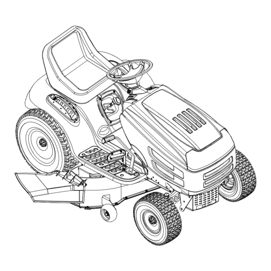
SECTION 4: KNOW YOUR GARDEN TRACTOR NOTE: Steering Wheel not shown for clarity. Figure 3 PTO (Power Take-off) Knob Cruise Control Button Choke Control Ignition Switch Parking Brake Button Brake Pedal Shift Lever Drive Pedal Cup Holder Deck Lift Lever Systems Indicator Monitor M Seat Adjustment Lever G Throttle Control Lever... - Page 10 Throttle Control Lever Ignition Switch The throttle control lever is located on the right side of Never leave running WARNING: the tractor’s dash panel. This lever controls the speed machine unattended. Always disengage PTO, of the engine. When set in a given position, the throttle move shift lever into neutral position, set will maintain a uniform engine speed.
- Page 11 Cub Cadet dealer. Seat Adjustment Lever The hour meter operates whenever the engine is running and records the actual hours of tractor...
-
Page 12: Operating Your Garden Tractor
• DO NOT MOW WHEN CHILDREN OR OTHERS ARE AROUND. Contact a Cub Cadet dealer. The safety interlock • NEVER CARRY CHILDREN, EVEN WITH BLADES OFF. • LOOK DOWN AND BEHIND BEFORE AND WHILE BACKING. - Page 13 Driving The Tractor WARNING: Keep hands and feet away from the discharge opening of the cutting WARNING: deck. Avoid sudden starts, ex- cessive speed and sudden stops. NOTE: The deck wheels are an anti-scalp feature of the deck and are not designed to support the weight of WARNING: Do not leave the seat of the the cutting deck.
- Page 14 Disengage the cruise control using one of the following This tractor is equipped with one of Cub Cadet’s high methods: quality cutting decks. The following information will be •...
-
Page 15: Making Adjustments
• Keep the blades sharp and replace the blades • Turn the key one notch counterclockwise into the when worn. Refer to Cutting Blades on page 18 of this On/Lights position of the ignition switch. Refer to manual for proper blade sharpening instructions. Figure 5. - Page 16 • Replace hex nut and lock washer and retighten the • The first measurement taken should be between jam nut after proper adjustment is achieved. 1/4" and 3/8" less than the second measurement. • Determine the approximate distance necessary for NOTE: Threading the ball joints too far onto the drag proper adjustment and proceed, if necessary, to the...
-
Page 17: Maintaining Your Garden Tractor
SECTION 7: MAINTAINING YOUR GARDEN TRACTOR WARNING: • Push the oil drain hose (packed with this manual) Before performing onto the oil drain port. Route the opposite end of maintenance or repairs, disengage PTO, the hose into an appropriate oil collection container move shift lever into neutral position, set with a capacity great enough to collect the used oil parking brake, stop engine and remove key to... -
Page 18: Service
SECTION 8: SERVICE Tires Blade Separation WARNING: Never exceed the maximum inflation pressure shown on the sidewall of the tire. Refer to the tire sidewall for exact tire manufacturer’s recommended or maximum psi. Do not overinflate. Worn Blade Edge Uneven tire pressure could cause the cutting deck to Wind Wing mow unevenly. - Page 19 • Always keep the battery cables and terminals clean • Looking at the cutting deck from the left side of the and free of corrosive build-up. tractor, locate the deck support pin on the rear left • After cleaning the battery and terminals, apply a side of the deck.
- Page 20 IMPORTANT: determine if you feel you could successfully complete it. the NEGATIVE (Black) wire from it’s terminal first, If you don’t, see a Cub Cadet dealer to have the belt followed by the POSITIVE (Red) wire. Re-install in changed. reverse order.
- Page 21 Drive belt (Lower) Variable-Speed Shift Lever Pulley Drive belt (Upper) Rear Idler Pulley Battery Tray Opening Front Idler Pulley Belt Keeper Keeper Pins Engine Pulley Double Idler Bracket Transmission Idler Pulley Idler Bracket Two-speed Transmission Pulley Transmission Front of Tractor NOTE: View shown from above tractor.
-
Page 22: Off-Season Storage
SECTION 10: ATTACHMENTS & ACCESSORIES The following attachments and accessories are compatible for Garden Tractor Model 1212. See your Cub Cadet dealer for information regarding price and availability. MODEL DESCRIPTION... -
Page 23: Troubleshooting
SECTION 11: TROUBLESHOOTING Trouble Possible Cause(s) Corrective Action Engine fails to start PTO knob engaged. Place knob lever in disengaged (OFF) position. Parking brake not engaged. Engage parking brake. Spark plug wire(s) disconnected. Connect wire(s) to spark plug. Throttle control lever not in correct Place throttle lever to FAST position. -
Page 24: Model 1212 Parts List
SECTION 12: MODEL 1212 PARTS LIST... - Page 25 Model 1212 REF. PART DESCRIPTION 683-0195 Bracket Assembly (8-style) 710-0599 Self-tapping Screw, 1/4-20 x .5 710-0751 Hex Cap Screw, 1/4-20 x .62 725-1976 Systems Indicator Monitor 710-1017 Truss Phillips Screw, 1/4-20 x .625 710-0351 Screw, #10-16 x .5 710-0376 Hex Cap Screw, 5/16-18 x 1.0...
- Page 26 Model 1212...
- Page 27 Model 1212 REF. PART REF. PART DESCRIPTION DESCRIPTION 747-1130A Deck Stabilizer Rod 736-3078 Flat Washer, .349 x 1.0 x .063 683-0197 Lift Shaft Assembly 783-0677 Lift Adjustment Bracket 711-0332 Clevis Pin, .5 x .78 783-0763B Fender 712-0206 Hex Nut, 1/2-13...
- Page 28 Model 1212...
- Page 29 Model 1212 REF. PART DESCRIPTION 710-1260A Self-tapping Screw, 5/16-18 x .75 710-0604A Self-tapping Screw, 16-18 x .625 683-0589 LH Pivot Support Bracket 683-0590 RH Pivot Support Bracket 783-0728 Pivot Bar Bracket 710-0514 Hex Cap Screw, 3/8-16 x 1 (Grade 5)
- Page 30 Model 1212 9 80...
- Page 31 Model 1212 REF. PART REF. PART DESCRIPTION DESCRIPTION 618-0375 Variable-speed Bracket Assembly 783-0669 Idler Bracket 618-0376 Two-speed Transmission Assembly 647-0031 Brake Control Shaft Assembly 631-0009A Shfter Knob 647-0032 Speed Control Shaft Assembly 647-0037 Shift Lever 683-0266 Drive Pedal Assembly 656-0050...
- Page 32 Model 1212...
- Page 33 Upon reassembling transmission input shaft for any reason, refill its cavity with approximately 2/3 oz. of grease. Order part number 737-0289. *Use applicable flat washer (44a, 44b or 44c) in this application allowing proper end-play as instructed in Cub Cadet’s Service Manual.
- Page 34 Model 1212...
- Page 35 Model 1212 REF. PART DESCRIPTION 783-0653D Steering Support Bracket 754-0476 PTO Belt 717-1709 Electric PTO Clutch 783-1003 Electric Clutch Anti-rotation Bracket 710-0859 Hex Cap Screw, 3/8-16 x 2.5 710-1238 Hex Head Washer Screw, 5/16-18 x .875 712-0431 Flange Lock Nut, 3/8-16 732-0978 Extension Spring, .62 x 5.62...
- Page 36 Model 1212...
- Page 37 Model 1212 REF. PART DESCRIPTION 16606 Retainer Hook 17982 Spindle Reinforcement Plate 618-0240A Spindle Assembly, 5.0 Dia. 756-1187 Pulley Only 618-0241 Double Pulley Spindle Assembly 756-0603 Double Pulley Only 683-0254 Deck Adjustment Bracket Assembly 683-0199C 46-inch Deck Shell 710-0167 Carriage Screw, 1/4-20 x .50 710-0344 Hex Cap Screw, 3/8-16 x 1.5...
- Page 38 Model 1212 (for choke) REF. PART REF. PART DESCRIPTION DESCRIPTION 710-0227 Self-tapping Screw, #8-18 x .5 751-0535 Fuel Line Hose 710-0599 Self-tapping Screw, 1/4-20 x .5 751-0564 Muffler Deflector 710-0604A Self-tapping Screw, 5/16-18 x .625 751-0616 Muffler, Twin Inlet 710-1237 Hex Screw, #10-32 x .625...
- Page 39 Model 1212...
- Page 40 MANUFACTURER’S LIMITED WARRANTY FOR: c. Log splitter pumps, valves and cylinders have a sepa- The limited warranty set forth below is given by Cub Cadet rate one year warranty. Corp. with respect to new merchandise purchased and d. Cub Cadet Corp. does not extend any warranty for used in the United States, its possessions and territories.
Need help?
Do you have a question about the 1212 and is the answer not in the manual?
Questions and answers