
Related Manuals for Cadet CLT-542H

Summary of Contents for Cadet CLT-542H
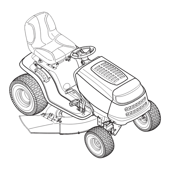
- Page 1 Operator’s Manual Hydrostatic Lawn Tractor Model: CLT-542H IMPORTANT: READ SAFETY RULES AND INSTRUCTIONS CAREFULLY CADET, 60 OTTAWA STREET SOUTH, KITCHENER, ONT. N2G 3S7 772C0745 PRINTED IN UNITED-STATES (01/05)
-
Page 2: Calling Customer Support
Copy the model number here: XXXXXXXXXXX XXX-XXXXXX Copy the serial number here: CUB CADET CANADA KITCHENER, ON N2G 4J1 ENGINE INFORMATION The engine manufacturer is responsible for all engine-related issues with regards to performance, power-rating, specifications, warranty and service. Please refer to the engine manufacturer’s Owner’s/Operator’s Manual packed separately with your unit for more information. -
Page 3: Section 1: Important Safe Operation Practices Warning
SECTION 1: IMPORTANT SAFE OPERATION PRACTICES WARNING: This symbol points out important safety instructions which, if not followed, could endanger the personal safety and/or property of yourself and others. Read and follow all instructions in this manual before attempting to operate this machine. Failure to comply with these instructions may result in personal injury. -
Page 4: Slope Operation
25. Disengage all attachment clutches, depress the 6. Keep all movement on the slopes slow and gradual. brake pedal completely and shift into neutral before Do not make sudden changes in speed or direction. attempting to start engine. Rapid engagement or braking could cause the front 26. -
Page 5: Safe Handling Of Gasoline
into reverse. The “Reverse Caution Mode” than ½ inch below bottom of filler neck to should not be used when children or others allow space for fuel expansion. are around. Replace gasoline cap and tighten securely. g. Keep children away from hot or running If gasoline is spilled, wipe it off the engine and engines. - Page 6 10. Never attempt to make adjustments or repairs to nal equipment specifications may lead to improper the machine while the engine is running. performance and compromise safety!” 11. Grass catcher components and the discharge 12. Do not change the engine governor settings or cover are subject to wear and damage which could over-speed the engine.
-
Page 7: Section 2: Attachments & Accessories
SECTION 2: ATTACHMENTS & ACCESSORIES. MODEL DESCRIPTION OEM-190-116 Mulch Kit (For 38” and 42” Decks) OEM-190-118 Mulch Kit (For 46” Decks) OEM-190-180 Twin Bagger Grass Collector 38” and 42” Decks OEM-190-182 Twin Bagger Grass Collector 46” Decks OEM-190-603 FastAttach Grille Guard (mounts on front of tractor) ™... -
Page 8: Section 3: Slope Gauge
SECTION 3: SLOPE GAUGE... -
Page 9: Section 4: Tractor Set-Up Note
SECTION 4: TRACTOR SET-UP NOTE: ATTACHING THE STEERING WHEEL Reference to RIGHT or LEFT side of the tractor in this manual is observed from operator’s In the event your tractor was crated with the steering position. wheel and the seat removed for shipping reasons, use the following instructions to properly assemble the ATTACHING THE BATTERY CABLES parts. -
Page 10: Attaching The Seat
ATTACHING THE SEAT Knob Adjustment Seat styles vary by tractor model and there are two different styles available: Knobs • Quick Adjustment • Knob Adjustment Shoulder Screws Refer to Figure 3 and Figure 4 to identify your tractor’s seat style and follow applicable instructions. Opening in Slot NOTE: For shipping reasons, seats are either... -
Page 11: Tire Pressure
IDENTIFYING THE MULCH PLUG (if so equipped) On tractor models with 42-inch and 46-inch decks so equipped, a mulch plug can be found within the cutting deck’s discharge opening. NOTE: Refer to '”Mulching“ on page 18 for more detailed information. If you’d prefer to operate the cutting deck without mulching, simply remove the mulch plug by unthreading the plastic wing nut which fastens it to the cutting deck. -
Page 12: Section 5: Controls
SECTION 5: CONTROLS NOTE: Steering Wheel not shown for clarity. A* PTO (Power Take-off) Lever (Models with manual PTO) Cruise Control Button PTO (Power Take-off) Knob (Models with electrique PTO) H Ignition Switch Systems Indicator Monitor/Hour Meter Brake Pedal Choke Control Drive Pedal Cup Holder Deck Lift Lever... - Page 13 the tractor’s dash panel. This lever controls the speed of IGNITION SWITCH the engine and, on some models, when pushed all the WARNING: Never leave a running machine way forward, the choke control also. When set in a unattended. Always disengage PTO, move given position, the throttle will maintain a uniform engine shift lever into neutral position, set parking speed.
- Page 14 SYSTEMS INDICATOR MONITOR / HOUR ELECTRIC PTO (POWER METER TAKE-OFF) KNOB Your tractor is equipped with either an hour meter or an To engage the power to the ammeter as part of two available system indicator cutting deck or other (separately monitors.
-
Page 15: Section 6: Operating Your Lawn Tractor Warning
CRUISE CONTROL PARKING BRAKE BUTTON BUTTON The cruise control button is To set the parking brake, fully located on the tractor dash panel depress the brake pedal and to the left of the ignition switch. push the parking brake button in. Push the cruise control button Hold the button in while taking while traveling forward at a... -
Page 16: Setting The Cutting Height
Reverse Caution Mode Reverse Push The REVERSE CAUTION MODE position of the key Indicator Button switch module allows the tractor to be operated in Light reverse with the blades (PTO) engaged. Reverse IMPORTANT: Mowing in reverse is not recommended. Caution Mode Stop Position WARNING:... -
Page 17: Driving The Tractor
STOPPING THE ENGINE If you strike a foreign object, WARNING: stop the engine, disconnect the spark plug Reverse Forward wire(s) and ground against the engine. Thoroughly inspect the machine for any damage. Repair the damage before restarting Brake Pedal and operating Drive Pedal •... - Page 18 NOTE: Cruise control cannot be engaged at the Front View Pull Out Push In tractor’s fastest ground speed. If the operator should attempt to do so, the tractor will automatically decelerate to the fastest optimal mowing ground speed. Disengage the cruise control using one of the following methods: •...
-
Page 19: Section 7: Making Adjustments Warning
• Do not mow at high ground speed, especially if a Carriage Screw mulch kit or grass collector is installed. • For best results it is recommended that the first two laps be cut with the discharge thrown towards the center. -
Page 20: Side To Side
The front of the deck should be between 1/4-inch and • Loosen the jam nut(s) on the rear side of the deck 3/8-inch lower than the rear of the deck. Adjust if stabilizer bracket. See Figure 15A. necessary as follows: •... -
Page 21: Parking Brake Adjustment
Crown Nut Seat Brake Disc Seat Adjustment Lever Figure 16 Hydrostatic Transmission Brake Rod NOTE: View shown from beneath tractor. Knobs Figure 18 STEERING ADJUSTMENT If the tractor turns tighter in one direction than the other, or if the ball joints are being replaced due to damage or wear, the steering drag links may need to be adjusted. -
Page 22: Section 8: Maintenance Warning
Front tire toe-in can be measured as follows: • Behind the axle, measure the distance horizontally from the inside of the left rim to the inside of the • Place the steering wheel in position for straight right rim. Note the distance. ahead travel. -
Page 23: Section 9: Lubrication Warning
Changing Engine Oil dusty condition. To service the air cleaner, refer to the separate engine manual packed with your unit. • Unscrew oil fill cap and remove dipstick from the oil The spark plug(s) should be cleaned and the gap reset fill tube. - Page 24 WARNING: Periodically inspect the blade BATTERY adapter and/or spindle for cracks or damage, The battery is sealed and is maintenance-free. Acid especially if you strike a foreign object. levels cannot be checked. Replace immediately if damaged WARNING: Shield eyes (e.g. goggles, face The blades may be removed as follows.
-
Page 25: Cutting Deck Removal
WARNING: Batteries give off an explosive gas while charging. Charge battery in a well ventilated area and keep away from an open flame or pilot light as on a water heater, space heater, furnace, clothes dryer or other gas appliances. GOOD Figure 24 JUMP STARTING... - Page 26 • Gently slide the cutting deck toward the front of the • With belt tension relieved, carefully remove the tractor allowing the hooks on the deck to release belt from around the left-hand spindle pulley. themselves from the deck stabilizer rod. 46-inch Decks with Electric PTO •...
-
Page 27: Hydrostatic Transmission
42-inch Deck (Electric PTO Shown) 46-inch Deck (Electric PTO Shown) Figure 28 HYDROSTATIC TRANSMISSION checked nor can the oil be changed. Always keep the area around the transmission cooling fan free of grass The hydrostatic transmission is sealed at the factory and debris at all times. -
Page 28: Section 12: Troubleshooting
• Clean the engine and the entire unit thoroughly. battery and make sure it has full charge. • Lubricate all lubrication points. Wipe the entire Disconnect the negative terminal of the battery machine with an oiled rag to protect the painted before storing the tractor. - Page 29 THREE (3) YEAR LIMITED WARRANTY For three (3) years from the date of original purchase of our products, we will either repair or replace, at its option, free of charge, F.O.B. Factory or authorized service firm, any part found to be DEFECTIVE IN MATERIAL and WORKMANSHIP for the original purchaser.
- Page 30 Style 1 *Refer to D and E on page 40./Référez-vous à D et E à la page 40.
- Page 31 REF. PART N°. DE N° DE RÉF. PIÈCE DESCRIPTION DESCRIPTION 710-0599 Hex Wash S-Tapp Scr 1/4-20 x .50 Vis autotaraudeuse à rondelle hex. 1/4-20 x 0,50 710-0642 Thd Forming Scr. 1/4-20 x .75 Lg. Vis taraudée 1/4-20 x 0,75 lg. 710-0726 Hex Wash HD AB Tap Scr 5/16 x .75 Vis taraudée 5/16 x 0,75...
- Page 32 Models w/Manually Adjusting Seat Modèles avec siège à réglage manuelle Models w/Quick-Adjust seat Modèles avec siège à réglage facile *Parts for 42” Deck only./Pièces pour plateau de coupe de 42 pouces seulement.
- Page 33 REF. PART N°. DE N° DE RÉF. PIÈCE DESCRIPTION DESCRIPTION 747-1130B Deck Stabilizer Rod Tige de stabilisation du plateau de coupe 683-04079 Lift Shaft Assembly (42” and 46” Deck) Arbre de relevage (plateau de coupe de 42 et 46 po) 683-04118 Lift Shaft Assembly (54"...
- Page 34 REF. PART N°. DE N° DE RÉF. PIÈCE DESCRIPTION DESCRIPTION 726-3046 Ratchet Clip .25 Dia. Attache 0,25 dia. 738-0296 Shoulder Bolt .437 Dia. x .268 Vis épaulée 0,437 dia. x 0,268 726-0201 Push Speed Nut Écrou rapide d'enfoncer 738-04012 Shoulder Spacer .625 x .175, 3/8-16 Entretoise épaulée 0,625 x 0,175, 3/8-16 720-04009 Knob, 3/8-16 x .625...
- Page 35 Notes...
- Page 36 Torque to 400-480 IN-LB/ Serrez à un couple de 400 - 480 po - lb Torque to 130-230 IN-LB/ Serrez à un couple de 130 - 230 po - lb Torque to 400-480 IN-LB/ Serrez à un couple de 400 - 480 po - lb Torque to 150-250 IN-LB/ Serrez à...
- Page 37 REF. PART N°. DE N° DE RÉF. PIÈCE DESCRIPTION DESCRIPTION 683-04173 Lower Frame Assembly Châssis inférieur 783-0726D RH Pivot Support Bracket Support de pivot CD 783-0727C LH Pivot Support Bracket Support de pivot CG 783-0728 Pivot Bar Bracket Support de la barre de pivotement 710-04095 Hex Cap Screw 3/8-16 x 1.00 Gr.
- Page 38 Detail A Détail A Wheel Chart / Tableau de roue 21 32 20 x 8 x 8 20 x 10 x 8 Square Shoulder Square Shoulder Épaule carré Épaule carré Description Wheel Ass'y Complete/ 634-0104 634-0177 Ensemble de roue complet Attach Spring Tire Only/Roue seulement 734-1730...
- Page 39 REF. PART N°. DE N° DE RÉF. PIÈCE DESCRIPTION DESCRIPTION 17840 Transaxle Mtg. Brkt. Support de montage de la transessieu 618-0319 Hydrostatic Transmission Transmission hydrostatique 629-0949A Reverse Wire Harness Adapter & Ground Adaptateur, fil de faisceau 783-04442 Double Idler Bracket Support de la poulie de tension double 710-1266 Hex Bolt 5/16-18 x 3.5"...
- Page 40 REF. PART N°. DE N° DE RÉF. PIÈCE DESCRIPTION DESCRIPTION 747-04093 Brake Lock Control Rod Tige de blocage du frein 748-04039B Cruise Latch Loquet du régulateur de vitesse 736-3008 Flat Washer .312 ID x .75 OD Rondelle plate 0,312 DI x 0,75 DE 783-04612 Steering Support Bracket Support de direction...
-
Page 41: Electrical System
Electrical System Système électrique 18/19 783-0715A REF ONLY/ 783-0715A REF ONLY/ COMME RÉFÉRENCE SEULEMENT COMME RÉFÉRENCE SEULEMENT Electric PTO harness shown. Manual PTO harness will vary slightly. Faisceau de fils à prise de force électrique illustré. Faisceau de fils à prise de force manuelle varie un peut. REF. - Page 42 � � � Ground Wire Ref. Only/ Fil masse comme référence seulement. 42-inch Deck Plateau 46 and 54 de coupe inch Deck � de 42 po †31 Plateau de coupe de 46 et 54 po * 46” Hydrostatic models only./Modèles hydrostatique de 46 po seulement. †...
- Page 43 REF. PART N°. DE N° DE RÉF. PIÈCE DESCRIPTION DESCRIPTION 683-04173 Lower Frame Assembly Châssis inférieur 710-0607 Hex Wash HD S-Tapp Scr 5/16-18 x .50 Vis auto-taraudeuse hexagonal 5/16-18 x 0,50 710-0642 Thd Forming Scr. 1/4-20 x .75 Lg. Vis taraudée 1/4-20 x 0,75 lg. 710-0726 Hex Wash HD AB Tap Scr 5/16 x .75 Vis taraudée 5/16 x 0,75...
- Page 44 Ground Wire Ref. Only/ Fil masse comme référence seulement 42-INCH DECK/ Plateau de coupe de 42 po 46-INCH DECK/ Plateau de coupe de 46 po Manual PTO/Prise de force manuelle...
- Page 45 REF. PART N°. DE N° DE RÉF. PIÈCE DESCRIPTION DESCRIPTION 647-0064 PTO Engage lever Assembly Levier d'enclenchement 710-0276 Carriage Bolt 5/16-18 x 1.00" Lg Boulon ordinaire de 5/16-18 x 1,00 po de lg. 710-0831 Hex Cap Screw, 3/8-16 x 1.5 Vis à...
- Page 46 REF. PART N°. DE N° DE RÉF. PIÈCE DESCRIPTION DESCRIPTION 756-04142 Engine Pulley 3.39 x 6.12 Dia 46" Trans. Poulie motrice 3,39 x 6,12 dia transmatique de 46 po 756-04143 Engine Pulley 3.56 x 6.12 Dia 46" Hydro Poulie motrice 3,56 x 6,12 dia hydrostatique de 46 po 647-04036 PTO Engage Lever Asssembly (2606G) Levier d'enclenchement (2606G)
- Page 47 Notes...
- Page 48 42-inch Deck Plateau de coupe 42 po Torque to 40-50 FT-LB/ Serrez à un couple de 40-50 pi - lb †50 †2 Tighten chute mtg. screws to 50-100 IN-LB/ Serrez les boulons du goulotte d'éjection à un couple de 50-100 po-lb Torque to 200-300 IN-LB/ Torque nuts to...
- Page 49 REF. PART N°. DE N° DE RÉF. PIÈCE DESCRIPTION DESCRIPTION 618-0624 Spindle Assembly 6.3 dia. Fusée dia. de 6,30 683-04138 Deck Brake Assembly (manual PTO) Frein du plateau de coupe (p.d.f. manuelle) 783-04491 Pivot Idler Bracket (Electric PTO) Support de tendeur de pivot (p.d.f. électrique) 683-04162 42"...
- Page 50 46-inch Deck Plateau de coupe 46 po †12 †50 †5 †63 †58 †53 †21 †61 †48 †46 †65 †49 †55 †67 †66 †59 †47 †54 †60 23 6 †45 2 18 †57 †12 †47 †62 †64 †55 710-0751 Torque to 50-150 FT-LBS/ †68 Serrez à...
- Page 51 REF. PART N°. DE N° DE RÉF. PIÈCE DESCRIPTION DESCRIPTION 618-0625 Spindle Ass'y 5.75 Dia w/grease fitting Fusée diamètre de 5,75 avec graisseur 683-0254B Deck Adjustment Bracket w/Weld Nut Support de réglage du plateau de coupe à écrou soudé 683-04104A 46" Deck Assembly w/Water Nozzle Plateau de coupe de 46 po avec orifice d'eau 710-0347 Hex Screw 3/8-16 x 1.75...
- Page 52 REF. PART N°. DE N° DE RÉF. PIÈCE DESCRIPTION DESCRIPTION 750-0566A Spacer .260 x .375 x 1.030 Lg. Entretoise 0,260 x 0,375 x 1,030 lg. 750-1320 Spacer .375 x .63 x .595 Entretoise 0,375 x 0,63 x 0,595 754-0349 V-Belt Courroie 754-04064 PTO Belt (w/46"...
- Page 53 Notes...
- Page 54 B&S OHV V-Twin B&S OHV Single (for throttle/pour le câble d'obturateur) (for choke/pour volet de départ) (deflector must face forward/ déflecteur doit faire face à l'avant) (deflector must face forward/ déflecteur doit faire face à l'avant) Tecumseh Twin Tecumseh Single (deflector must (deflector must face forward/...
- Page 55 REF. PART N°. DE N° DE RÉF. PIÈCE DESCRIPTION DESCRIPTION 710-0227 Hex Wash HD AB S-Tapp Scr #8 x .50 Vis taraudée n°. 8 x 0,50 710-0599 Hex Wash S-Tapp Scr 1/4-20 x .50 Vis autotaraudeuse à rondelle hex. de 1/4-20 x 0,5 710-0726 Hex Wash HD AB Tap Scr 5/16-12 x .75 Vis taraudée 5/16-12 x 0,75...
- Page 56 Notes...
- Page 57 Notes...
Need help?
Do you have a question about the CLT-542H and is the answer not in the manual?
Questions and answers