
Related Manuals for ALPhANOV AeroDIODE Cool & Control Series

Summary of Contents for ALPhANOV AeroDIODE Cool & Control Series
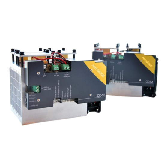
- Page 1 Operating manual Cool & Control Series CCM Multi-Mode laser diode driver AERODIODE - Institut d’optique d’Aquitaine - Rue François Mitterrand 33400 Talence - France - Tél.: +33 (0)6 27 69 41 62 www.aerodiode.com...
-
Page 2: Table Of Contents
Contents General information ............................. 3 1.1. Definitions ..............................3 1.2. General warning ............................3 Safety Instructions ............................... 4 2.1. Wiring ................................. 4 2.2. Operating Environment ..........................4 2.3. Contact ............................... 5 Product overview ..............................5 3.1. Physical properties* ........................... 5 3.2. -
Page 3: General Information
1. General information Please read this manual carefully, it describes the hazard the user might be exposed to while using the product. It also explains in details how to use the product in the safest and more efficient way possible. The safety of any system incorporating the product is the responsibility of the assembler of the system. -
Page 4: Safety Instructions
WARNING Avoid all chocs and strains when handling the CCM. WARNING Handle the fiber-optics with care as it is fragile. Do not bend or pinch it. WARNING Any software settings or hardware tinkering that is not described in this user manual or in the usage recommendation may put the user or its environment at risk. -
Page 5: Contact
WARNING Not following the safety recommendations and the caution mentioned above can lead to eye damage. 2.3. Contact If you have any question about the CCM module, please contact AERODIODE. 3. Product overview 3.1. Physical properties* Product Length(mm) Width(mm) Height(mm) Weight(kg) CCM 60W CCM 120W... - Page 6 Power supply location for the CCM device (24 Vdc / 20 A), use cables with 16AWG gauge 2. Power ON indicator Blue LED indicates that the device is powered 3. Alarm indicator Red LED indicates that an extreme condition is reached and has triggered the laser extinction (Interlock open, CPU dysfunction or overheating) 4.
- Page 7 12. Monitoring current Allows current monitoring when using the device without the software (185 mV/A) [left : signal / right : GND] 13. CTN CTN connector input for measuring and controlling the laser diode temperature 14. TEC output Electrical output location for thermoelectric cooler supply 15.
-
Page 8: Installation
4. Installation The CCM driver is able to drive any type of laser diode until 150W / 36 V / 21 A 4.1. Laser diode installation for efficient thermal regulation Caution Care must be taken in order to properly cool the laser diode. In case of bad thermal contacts of the diode and thermistor, the regulation may be unstable. - Page 9 Choose the one that best suits your setup, take into consideration the size of your diode, the length of the power cables of your diode and TECs. They should easily reach their respective connectors, while not being to tensed to avoid any strain on the solders. In this example, the chosen spot is the (1).
- Page 10 (B) Spread some thermal grease on the top surface of the thermoelectric cooler and then lay down the diode on top of it. Again, please take care not to introduce any thermal contact between both plates of the TEC. To optimize thermal efficiency, if the diode is small compared to the thermoelectric cooler, you can paste a piece of thermal conductive sheet (graphite for example) going from the thermoelectric cooler to the laser diode sides.
-
Page 11: Wiring
4.2. Wiring 1) Plug your TEC(s) power cables here, respect the polarity as show above 2) Plug your Diode power cables here, respect the polarity as show above Page 11/28 – v3.4... -
Page 12: Example Of Multiple Laser Diodes And Tec Connected To One Ccm
4.3. Example of multiple laser diodes and TEC connected to one CCM On the picture below, two IPG laser diodes are connected in Serial to a CCM device with only one TEC. On the front page of this manual, three BWT laser diodes are connected in serial to a CCM with three TEC (one for each laser diode) also connected in serial. -
Page 13: Mechanical Holding
4.4. Mechanical holding Screw the holding plate on top of the laser diode in order to hold the laser diode and guarantee good thermal efficiency. WARNING The Holding plates should be screwed with a torque of 15cN.m. Too much pressure may damage the TEC and too low pressure will not perform good uniform thermal contact with the TEC. -
Page 14: Getting Started
5. Getting Started 5.1. Software installation Caution The CCM USB specific cable should be unplugged during the installation. Note Please note that the USB cable can also be unplugged after the board has been configured. Double-click on setup.exe to run the installer. The control software will be installed, as well as the driver for the USB cable. - Page 15 Click on the “ALPhANOV Control Software” item located in the Start Menu in order to run the CCM control software. A window appears: Click on Connect to start the CCM hardware detection. The software automatically detects any USB-connected AeroDIODE devices.
-
Page 16: Software Overview
5.2. Software overview Laser Max. levels Enable Controls Parameters Measurements Alarms Page 16/28 – v3.4... - Page 17 The window is split in six parts: 1. MAX LEVELS: The maximum current and voltage values are settable in the Max levels part and must be chosen in accordance to the laser diode specifications and operating data everytime a new laser diode is mounted on the CCM module (see bellow). The floppy disk logo indicates that these values can be stored into the CCM memory (upon clicking) 2.
-
Page 18: Setting The Limits
5.3. Setting the limits The CCM laser diode driver includes hardware overcurrent and overvoltage protections requiring to be set up before to drive any laser diodes. Please mind to configure these values to their maximums as recommended by the laser diode supplier. -
Page 19: Control Mode
5.5. Control mode This two-position switch controls the operating mode (current or power control) Direct Current Control / Automatic Power Control Save the photodiode signal level for the constant power mode (see Page 6) 5.6. CW/pulse operation This two-position switch controls the operating mode (CW or pulse). Select if the laser diode is operated continuously (CW) or pulsed A new window will pop up on click: pulse settings •... -
Page 20: Settings
• Gate Mode: if set to None, the CCM laser driver will deliver pulses while the laser is enabled. If set to Soft, the laser emission will stop after reaching the burst count. • Burst Count: number of pulses in Soft Gate Mode (1-255 range) •... -
Page 21: Measurements
5.8. Measurements Indicates the current passing through the laser diode Indicates the laser diode voltage Indicates the laser diode temperature measured by the mobile CTN. A negative value indicates that the CTN is disconnected Indicates the electronic temperature measured by a CTN placed on a sensitive electronic component. -
Page 22: Alarms
5.9. Alarms Red light indicates that the laser diode temperature has crossed over the maximum value (default is 45°C). Orange light indicates that the CTN cable is disconnected Red light indicates that a sensitive electronic component has reached a critical high temperature. Orange light indicates that the CTN cable is disconnected Red light indicates that the chosen voltage differs from the diode’s nominal voltage. -
Page 23: Menu Bar
5.10. Menu bar File o Load parameters Click on this item to load a .txt file which contains the operating parameters. o Save parameters Click on this item to save the current parameters into a .txt file. This file can be loaded using the “Load parameters”... -
Page 24: Configuration Examples
6. Configuration examples 6.1. How to run the laser in CW/pulse mode with the GUI* In CW mode : Make sure that the “Fonctionment Mode” is on “CW”. Write in “Diode Curr.” The diode current you would like to apply in the laser diode. Choose between “Man”... -
Page 25: Use Of Optional Tombak To Generate Full Adjustable Pulses
6.2. Use of optional TOMBAK to generate full adjustable pulses The CCM could be used with a TOMBAK product to pulsed the high power laser diode. In this case, the TOMBAK can be mounted/unmounted on the other side of the heat sink as shown below. - Page 26 The TOMBAK could then be powered up using the dedicated 5V DC power supply. The CCM could also be powered up using the 24V DC power-supply. The products need to be connected to the computer using two USB/jack cables or using one USB/jack cable to the computer and a jack/jack cable to the other product using the daisy chained functionality (Daisy-Out connector of a product to USB-In of the second).
- Page 27 Page 27/28 – v3.4...
-
Page 28: Technical Specification
7. Technical specification 7.1. General Data Length Width Height Weight Power connector (Wires)* mm² Power supply (DC) 24 Vdc / 20 A *Minimum wire section 7.2. Detailed data Operating temperature -15°C +40°C Storage temperature -25°C +70°C Operating Altitude 2000m Page 28/28 – v3.4...
Need help?
Do you have a question about the AeroDIODE Cool & Control Series and is the answer not in the manual?
Questions and answers