PIONEER DJ XDJ-700 Service Manual
Multi player
Hide thumbs
Also See for XDJ-700:
- Operating instructions manual (37 pages) ,
- Service manual (26 pages) ,
- Connection manual (15 pages)
Table of Contents
Advertisement
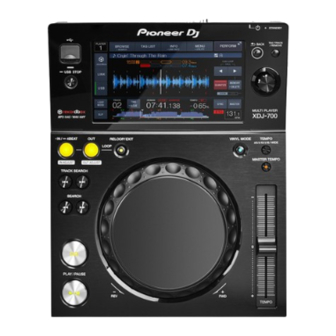
MULTI PLAYER
XDJ-700
THIS MANUAL IS APPLICABLE TO THE FOLLOWING MODEL(S) AND TYPE(S).
Model
Type
XDJ-700
UXJCB
XDJ-700
SYXJ
XDJ-700
FLXJ
XDJ-700
AXJ
THIS SERVICE MANUAL SHOULD BE USED TOGETHER WITH THE FOLLOWING MANUAL(S).
Model
XDJ-700
PIONEER CORPORATION
PIONEER ELECTRONICS (USA) INC. P.O. Box 1760, Long Beach, CA 90801-1760, U.S.A.
PIONEER EUROPE NV Haven 1087, Keetberglaan 1, 9120 Melsele, Belgium
PIONEER ELECTRONICS ASIACENTRE PTE. LTD. 253 Alexandra Road, #04-01, Singapore 159936
Pioneer DJ Corporation 2015
Power Requirement
AC 100 V to 240 V
AC 100 V to 240 V
AC 100 V to 240 V
AC 100 V to 240 V
Order No.
RRV4638
SCHEMATIC DIAGRAM, PCB CONNECTION DIAGRAM, PCB PARTS LIST
1-1, Shin-ogura, Saiwai-ku, Kawasaki-shi, Kanagawa 212-0031, Japan
XDJ-700
Remarks
K-MZV NOV.
ORDER NO.
RRV4637
Remarks
2015 Printed in Japan
Advertisement
Table of Contents

Related Manuals for PIONEER DJ XDJ-700


Summary of Contents for PIONEER DJ XDJ-700
- Page 1 PIONEER ELECTRONICS (USA) INC. P.O. Box 1760, Long Beach, CA 90801-1760, U.S.A. PIONEER EUROPE NV Haven 1087, Keetberglaan 1, 9120 Melsele, Belgium PIONEER ELECTRONICS ASIACENTRE PTE. LTD. 253 Alexandra Road, #04-01, Singapore 159936 Pioneer DJ Corporation 2015 K-MZV NOV. 2015 Printed in Japan...
-
Page 2: Safety Information
PIONEER Service Manual. A subscription to, or additional copies of, Also test with plug reversed Earth PIONEER Service Manual may be obtained at a nominal (Using AC adapter ground charge from PIONEER. plug as required) AC Leakage Test XDJ-700... -
Page 3: Table Of Contents
• For environmental protection, lead-free solder is used on the printed circuit boards mounted in this unit. Be sure to use lead-free solder and a soldering iron that can meet specifications for use with lead-free solders for repairs accompanied by reworking of soldering. Do NOT use a soldering iron whose tip temperature cannot be controlled. XDJ-700... -
Page 4: Notes On Replacing Parts
If the ICP is damaged, no buttons or LEDs of the unit will light and nothing will be displayed when the POWER switch is set to ON. 29-pin flexible cable MAIN Assy PNLB Assy CN1103 CN2001 Control panel Section • Bottom view XDJ-700... -
Page 5: Specifications
Port ..................Type B LAN (PRO DJ LINK) Rating ................100Base-TX Main display Display type ....Active matrix TFT liquid crystal display (LCD) Supported languages ..........18 languages • The specifications and design of this product are subject to change without notice. XDJ-700... -
Page 6: Basic Items For Service
The zipped writing tool (mmpforseigi.exe) and data file (hidcom.dll) are posted at Niis. See "8.3 WRITING THE SERIAL NUMBER OF THE UNIT." Lubricants and Glues List Name Part No. Remarks Lubricating oil GYA1001 Refer to "9.4 JOG DIAL SECTION". XDJ-700... -
Page 7: Pcb Locations
Therefore, when replacing, be sure to use parts of identical designation. Mark No. Description Part No. LIST OF ASSEMBLIES 1..MAIN ASSY DWX3744 1..PNL ASSY DWM2581 2..PNLB ASSY DWX3745 2..JOGB ASSY DWX3746 2..TCHB ASSY DWX3747 2..PSWB ASSY DWX3748 2..USBA ASSY DWX3749 2..TXLB ASSY DWX3750 XDJ-700... -
Page 8: Block Diagram
4. BLOCK DIAGRAM USB CONNECTOR TFT-LCD MODULE (CWX4352) (A TYPE) CN1101 *HORIZONTAL CKS6625-A CN701 JA2801 L=50mm CKS4428-A POWER CORD DKB1118-A *RIGHT ANGLE BLACK Anode AC ADAPTER TOUCH PANEL (DSX1130) Cathode (DWR1546-) WHITE USBA ASSY Use "megane" type POWER CORD FPC 0.5mm Pitch 28mm DESTINATION Part Number Polarity... -
Page 9: Signal Block Diagram
MAIN ASSY USBA ASSY CN2801 CN1201 USB_STOP (LED) USB STOP USB STOP C15,D15 DYW**** (NSP) (MX29LV640ETTI-70G) CN2701 CWX4352- JH2001 DYW**** (R5F364AENFA-U0) PSWB ASSY JOGB ASSY CN2501 IC701 13,14,15 CN2004 CN2601 CN2005 TCHB ASSY MAIN ASSY PNLB ASSY... -
Page 10: Power Supply Block Diagram
AC Adapter MAIN ASSY PNLB ASSY Q1301 Q1304 IC1301 DWR1546-A JA1301 CN1103 CN2001 V+12 V+12_ADP V+12ADP V+12E V+12E DCDC V+3R3E V+3R3E BD9328EFJ PANEL CPU FUSE P1301 Q1308 1.586MYR Mute IC854 CPMP V+12A NJW4191R V-9A BEAD V+3R3E STBY LED OPamp IC856 V+12A NJM2831F09 V+9A... -
Page 11: Diagnosis
Register setting of ETHER PHY • USB_A • USB_B • ETH_MAC Initialization of the • SERIAL built-in peripherals • SSI Communication between MAIN CPU and PANEL CPU Canceling reset LED initial lighting Apple authentication chip Opening screen display Device select screen XDJ-700... -
Page 12: Troubleshooting
[1-1] No power Cause Diagnostics Point Item to be Checked Corrective Action Reference The AC adapter AC adapter Check V+12. If V+12 (JA1301 pin 1) is not output, ————— does not function the AC adapter is defective. Replace it. properly. XDJ-700... - Page 13 Replace it. Defective PANEL PNLB Assy If the symptom persists after the above Check the connection between the PANEL CPU ————— corrections. (IC2001) and the LED in question. If the connection is OK, the port may be damaged. Replace it. XDJ-700...
- Page 14 ENC1 and ENC2 must change. Defective PANEL PNLB Assy If the symptom persists after the above Check the connection of the PANEL CPU ————— corrections. (IC2001). If the connection is OK, the port may be damaged. Replace it. XDJ-700...
- Page 15 Replace the Washer, Load gear, and Cam plate with new ones, then reassemble. After replacement, adjust the position of the Cam plate to change the load value for the Jog dial. XDJ-700...
- Page 16 (X3-pin 3) Correct loose connection. If the symptom persists, replace the defective part. Defective MAIN Assy If the symptom persists after the above The MAIN CPU (IC8) is defective. ————— MAIN CPU corrections. Replace the MAIN Assy. XDJ-700...
- Page 17 DAC (IC852) or one of its (IC852 pin 7, 8). peripheral parts may be defective. If the digital signal is not input, DSP (IC301) or one of its peripheral parts may be defective. Correct loose connection. If the symptom persists, replace the defective part. XDJ-700...
- Page 18 Check the connections between DSP (IC301) ————— between the MAIN DSP and SDRAM. and SDRAM (IC302). DSP and SDRAM If soldering is improper, resolder it. ————— ————— If the symptom persists after the above Replace the MAIN Assy. ————— corrections. XDJ-700...
- Page 19 After checking the voltages, be sure to reattach Q2603. Q1204. ————— ————— If the symptom persists after the above Replace the MAIN Assy then the PNLB Assy, in that order, ————— corrections. one by one, followed by a startup check after each replacement. XDJ-700...
-
Page 20: Connection Confirmation With The Pc
If the indication changes from 1 to 2 then 3, the link is properly established. If the cable is disconnected, the indication returns to 1. 5. After checking is completed, press the MENU/UTILITY key. The screen displayed before the MENU/UTILITY key was pressed will be restored XDJ-700... -
Page 21: Service Mode
: The point moves according to the direction that Jog dial turned. ENCODER : The point moves according to the direction that ENCODER switch turned. TEMPO SLIDER VOLUME : If a TEMPO slider knob is moved to the − side, a bar display will increase. XDJ-700... - Page 22 Colorbar All-white screen All-green screen All-blue screen Confirmation of the Touch display operation Display LCD color patterns, as mentioned above, then select an all-black screen. Touch the screen and verify that a plus sign lights at the touched position. XDJ-700...
- Page 23 8.68 In addition, data is added whenever it pushes MASTER TEMPO button. 7.12 Moreover, the MAC address is filled in as solid identification. 8.17 8.68 8.17 8.54 7.82 8.24 137(NG) (judge : 85 ms <= Time <= 115 ms) XDJ-700...
- Page 24 : The microcomputer which controls a button input. : Audio DSP PHY CHIP : The controller which controls the physical layer of Ethernet. AUTH CHIP : The authentication tip of Apple. Please refer to "[6] Output of the alarm port" for details. XDJ-700...
- Page 25 • JOG rotation (except for touching the Table top) • Turn the TOUCHR/ELEASE volume • Move the TEMPO slider It will return from the auto standby mode. Since a return is the same processing as power supply ON, the service mode is ended. XDJ-700...
- Page 26 It is the format which is not supported. E-8306 NO FILE The registered file does not exist. E-8307 USB ACCESS ERROR USB apparatus which is not supported was connected. E-8309 LINK ACCESS ERROR It ended in the error of the timeout of continuation 4 times. XDJ-700...
- Page 27 3 Auto device diagnosis of a "[3] Indication of various information", the test port output on a main board can also be checked. When a defect is detected by the device by power supply ON, an alarm port performs the following pulse outputs. XDJ-700...
- Page 28 Please continue pushing a button until it turns on a power supply and the message of "Connect a USB storage device to the USB port." is displayed, pushing only a USB-STOP button. In addition, if files other than PANEL are contained in USB memory, it will usually pass and all they will be updated. XDJ-700...
-
Page 29: About The Device
The "****" part of the part number changes each time the firmware is updated. Two or more FLASH and SDRAM are mounted in the main unit. Please diagnose it after confiming whether it is a device that agrees with purpose again. XDJ-700... -
Page 30: Disassembly
Even if the unit shown in the photos and illustrations in this manual may differ from your product, the procedures described here are common. Disassembly [1] Bottom Section (1) Remove the 2 screws. (BBZ30P060FTB) (2) Remove the 4 screws. (BPZ30P080FNI) • Rear view Front • Bottom view (3) Remove the Bottom section. Bottom section Control panel section XDJ-700... - Page 31 (1) Remove the Bridge, by removing the 3 screws. Bridge (BBZ30P060FTB) Screw tightening order • Bottom view (2) Remove the 2 screws. (BBZ30P060FTB) (3) Remove the USBA Assy, by disconnecting the 1 BtoB connector. (CN2801) CN2801 USBA Assy Screw tightening order • Bottom/Rear view XDJ-700...
- Page 32 (4) Remove the 1 screw. (BPZ30P080FNI) (5) Remove the 1 screw. (DBA1340) (6) Remove the Shield case. Screw tightening order [2-5] Diagnosis (1) Reconnect the 1 flexible cable. (CN1103) Diagnosis MAIN Assy CN1103 (2) Disconnect the 1 flexible cable. (CN1103) Control panel section XDJ-700...
- Page 33 (3) Remove the MAIN Assy, by removing the CN1101 2 screws. (BBZ30P060FTB) Screw tightening order CN701 MAIN Assy • Bottom view [2-7] TFT LCD (1) Remove the Stay, by removing the 4 screws. (BPZ26P080FTC) Screw tightening order • Bottom view Stay XDJ-700...
- Page 34 (2) Remove the TFT LCD. (3) Remove the Touch panel. Jumper wire styling TFT LCD TFT LCD Touch panel To MAIN Assy CN701 [3] PNLB Assy (1) Disconnect the jumper wire. PSWB Assy (CN2701) CN2701 (2) Remove the Knob/SLD. XDJ-700...
- Page 35 (CN2004, 2005) (4) Remove the PNLB Assy with Sheet, by removing the 13 screws. (BPZ30P080FNI) CN2004 CN2005 • Bottom view Screw tightening order The other screws are random order. Jumper wire and Sheet styling Sheet Sheet Jumper wire Jumper wire XDJ-700...
- Page 36 (1) Release the jumper wire from the 2 hooks. (2) Remove the Lever holder with PC board, by Lever holder removing the 3 screws. (BPZ20P060FTC) Screw tightening order • Bottom view Lever holder (3) Remove the TCHB Assy, by removing the 1 screw. (BPZ20P060FTC) TCHB Assy XDJ-700...
- Page 37 (2) Remove the Arm section with PC board, by removing the 1 screw. (DBA1265) Arm section • Bottom view (3) Remove the JOGB Assy, by removing the 2 screws. (BPZ20P060FTC) JOGB Assy ×2 Jumper wires styling JOGB Assy TCHB Assy PNLB Assy CN2004 CN2005 XDJ-700...
-
Page 38: Each Setting And Adjustment
OK. 3 Enter a "$CDJ" command then click on OK. 6 Enter a "?N" command then click on OK to check the serial 4 Enter a "1MC" command then click on OK. number. XDJ-700... -
Page 39: Jog Dial Rotation Load Adjustment
[Load adjustment method] • When smaller than 85 msec. ⇒ Adjust the Cam plate to minus"-" side. (To decrease the load) • When bigger than 115 msec. ⇒ Adjust the Cam plate to plus"+" side. (To increase the load) XDJ-700... -
Page 40: Items For Whitch Users Setting Is Available
4. Use the rotary selector to select and enter [SAVE] at [MY SETTINGS]. Restore (Retrieving the stored settings) 1. Sets the USB device for calling out the setting details. 2. Touch [USB]. 3. Touch [MENU (UTILITY)]. 4. Use the rotary selector to select and enter [LOAD] at [MY SETTINGS]. XDJ-700... -
Page 41: Exploded Views And Parts List
For the applying amount of lubricants or glue, follow the instructions in this manual. (In the case of no amount instructions, apply as you think it appropriate.) 9.1 PACKING SECTION SYXJ only FLXJ only Stand • Bottom view AXJ only AXJ only AXJ only XDJ-700... - Page 42 19 Packing Case See Contrast table (2) NSP 20 Polyethylene Bag AHG7117 NSP 21 Poly Bag DHL1198 (2) CONTRAST TABLE XDJ-700/UXJCB, SYXJ, FLXJ and AXJ are constructed the same except for the following: XDJ-700 XDJ-700 XDJ-700 XDJ-700 Mark Symbol and Description...
-
Page 43: Exterior Section
9.2 EXTERIOR SECTION Refer to • Bottom view "9.3 DISPLAY SECTION". Refer to "9.4 JOG DIAL SECTION". • Bottom view XDJ-700... - Page 44 19 Button DAC3146 20 Slide Sheet 1C DAH2404 21 Panel DAH3056 22 Sheet DEC3624 23 Knob/SLD DNK5981 24 Control Panel DNK6527 25 Chassis DNK6521 26 ..27 Screw BBZ30P060FTB 28 Screw BPZ30P080FNI 29 Screw BPZ30P080FTB XDJ-700...
-
Page 45: Display Section
9.3 DISPLAY SECTION PNLB CN2001 XDJ-700... - Page 46 DNH3236 12 Bridge DNH3242 13 Base DNK6525 14 Rear Panel DNK6528 15 Tape DEC3655 16 ..17 ..18 Screw BBZ30P060FTB 19 Screw BPZ26P080FTC 20 Screw BPZ30P080FNI 21 Screw (M3*5) DBA1340 XDJ-700...
-
Page 47: Jog Dial Section
9.4 JOG DIAL SECTION • Bottom view Hook Hook Arm spring PNLB PNLB CN2004 CN2005 Grease (GYA1001) • Holder • Jog shaft 5 mm 5 mm XDJ-700... - Page 48 20 Jog Dial DNK6522 21 Arm DNK6523 22 Holder DNK6524 23 Roller A Assy DXB1825 24 ..25 ..26 Washer WA41D070D025 27 Washer WT32D080D050 28 Screw BPZ20P060FTC 29 Screw (FE) DBA1265 XDJ-700...
Need help?
Do you have a question about the XDJ-700 and is the answer not in the manual?
Questions and answers