Table of Contents
Advertisement
Quick Links
Technical Support and E-Warranty Certificate www.vevor.com/support
MULTIMETER
We continue to be committed to provide you tools with competitive price.
"Save Half", "Half Price" or any other similar expressions used by us only represents an
estimate of savings you might benefit from buying certain tools with us compared to the major
top brands and doses not necessarily mean to cover all categories of tools offered by us. You
are kindly reminded to verify carefully when you are placing an order with us if you are
actually saving half in comparison with the top major brands.
Advertisement
Table of Contents

Subscribe to Our Youtube Channel
Related Manuals for VEVOR PM8225D


Summary of Contents for VEVOR PM8225D
- Page 1 Technical Support and E-Warranty Certificate www.vevor.com/support MULTIMETER We continue to be committed to provide you tools with competitive price. "Save Half", "Half Price" or any other similar expressions used by us only represents an estimate of savings you might benefit from buying certain tools with us compared to the major top brands and doses not necessarily mean to cover all categories of tools offered by us.
- Page 2 CustomerService@vevor.com This is the original instruction, please read all manual instructions carefully before operating. VEVOR reserves a clear interpretation of our user manual. The appearance of the product shall be subject to the product you received. Please forgive us that we won't inform you again if...
-
Page 3: Table Of Contents
Please read the instructions carefully before use. Catalogue Statement ......................3 Summary ....................... 3 Safety instructions ....................3 Safety symbol ......................4 Safe operation specifications ................4 Instrument instructions ..................6 LCD symbol instructions ..................8 Measurement instructions ..................9 AC and DC voltage measurement ................ -
Page 4: Statement
Statement According to the Universal Copyright Convention, without permission and written consent, no content of this manual may be reproduced in any form (including storage and retrieval or translation into the languages of other countries or regions). This manual is subject to change in future versions without extra notice. Caution The "caution"... -
Page 5: Safety Symbol
Safety symbol Please refer to the instructions for important safety information AC high voltage danger Non-recyclable The fuse must be replaced according to the designated specification in the manual. Safe operation specifications Warning To avoid possible electric shock or physical injury, please comply with the following specifications: ·... - Page 6 · Do not use the HOLD function to measure unknown voltage. After HOLD is turned on, the display screen will not change when different voltages are measured. · Measure a known voltage to determine whether the instrument operates normally. · When measuring, the correct function and range gear must be used. ·...
-
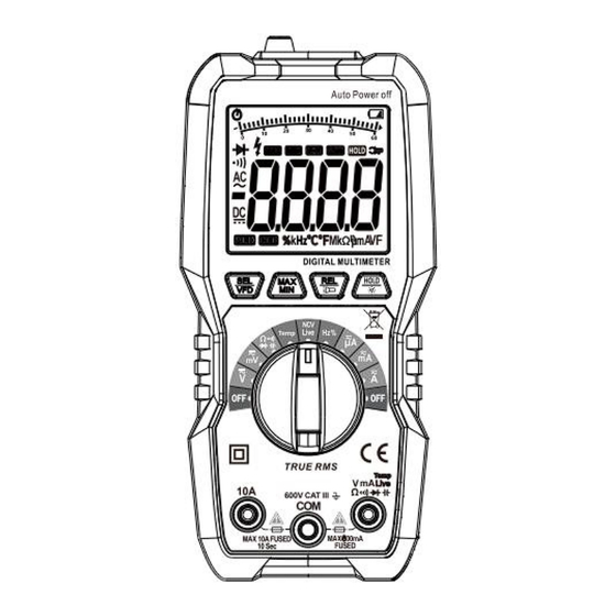
Page 7: Instrument Instructions
Instrument instructions ①.LCD display: It is with 4 digit 7-segment nixie tube display, 6000 counts, and analog bar indication function. ②. Key area: Function selection key: Briefly press the key to switch gear function, and long press the key for about 2 seconds to turn on or turn off VFD low-pass filter. Attention: VFD low-pass filter only works at AC voltage gear ( ). - Page 8 long press the key for about 2 seconds to exit the maximum or minimum value measurement. Relative value measurement/ Lighting key: Briefly press the key to turn on or turn off the relative value measurement, and long press the key for about 2 seconds to turn on or turn off the light. Data retention / LCD backlight key:...
-
Page 9: Lcd Symbol Instructions
LCD symbol instructions Automatic shutdown indicator Capacitance unit Diode measurement indicator Current unit Connectivity measurement Voltage unit indicator AC indicator Data display area Data minus indicator Display retention key DC indicator Analog bar indication VFD low pass filter indicator Battery low voltage indicator Relative measurement Contact live wire electricity indicator... -
Page 10: Measurement Instructions
Measurement instructions Precautions before operation: 1. Turn on the power and check whether the battery is under voltage. If " " is displayed on the screen, you need to replace the battery before operation. If not, please follow the steps below. 2. -
Page 11: Mv Gear Voltage Measurement
3. Press " " key to switch DC voltage, AC voltage, frequencyand duty ratio, AC voltage mode long press it to turn on or turnoff VFD function. Attention: 1. Before turning the function rotary switch, leave the measurement probe from the circuit under measurement. 2. -
Page 12: Resistance/Connectivity/Diode/Capacitance Measurement
4. Pay special attention to avoid electric shock when measuring high voltage. Resistance/connectivity/diode/capacitance measurement 1. Insert the red probe into the " " jack and the black probe into the jack. 2. Turn the knob switch to the " " position and press the key to switch the measurement of resistance, connectivity, diode and capacitance. -
Page 13: Non-Contact Electricity Verification (Ncv) / Live Wire Detection (Live)
Non-contact electricity verification (NCV) / Live wire detection (Live) 1. Turn the knob switch to the " " position and press the key to switch NCV or Live function. 2. Under the NCV function, place the NCV sensing area close to the wire to be measured. -
Page 14: Frequency / Duty Ratio
Warning: 1. Measurement range: about 36V~600V, 50Hz or 60Hz. 2. When using, even if there is no sound or display prompt, the wire to be measured may still have voltage. The instrument may be affected by other factors (such as shielded wires and cables, thickness of insulation layer, distance from voltage source, diversity in socket design, etc.), and fail to sense the electric field. -
Page 15: Ma Current
2. Turn the knob switch to the " " position and press the key to switch the AC current, DC current or frequency measurement. 3. Connect the measurement probe in series to the load, and the polarity of the red probe connection will be displayed when the current value is displayed. -
Page 16: A Current
4. Do not input a current with an effective value higher than 600uA, otherwise there is a risk of damaging the instrument. A current 1. Insert the red probe into the " " jack and the black probe into the jack. -
Page 17: Accuracy Index
· The maximum allowable voltage between the measuring terminal and the ground: 600V DC or AC RMS. · Sampling rate: about 3 times / second · Automatic shutdown: about 10 minutes. · 6000 Display: the maximum displayed value is 6000 ·... - Page 18 DC voltage Range Resolution Accuracy 60mV 10uV 600mV 100uV ± (0.5% reading +3 digits) 10mV 600V 100mV 600V Maximum allowable measurement voltage: 600V Resistance Range Resolution Accuracy 600Ω 0.1Ω 6kΩ 1Ω ±(1.2% reading +5 digits) 60kΩ 10Ω 600kΩ 100Ω 6MΩ 1kΩ...
- Page 19 0.001mF ±(4.0% reading +5 digits) 10mF 0.01mF 100mF 0.1mF ±(5.0% reading +5 digits) Over voltage protection: 600V DC or AC RMS Frequency Range Resolution Accuracy 10Hz 0.001Hz 100Hz 0.01Hz ±(1.0% reading +5 digits) 1kHz 0.1Hz 10kHz 100kHz 10Hz 1MHz 100Hz 10MHz 1kHz Minimum input voltage: 200mV (RMS)
-
Page 20: Instrument Maintenance
Frequency range: 40Hz~1000Hz DC current Range Resolution Accuracy 600uA 0.1uA ±(0.8% reading +3 digits) 60mA 10uA 600mA 100uA ±(1.0% reading +3 digits) ±(1.2% reading +3 digits) 10mA Maximum input current of mA jack: 600mA Maximum input current of 10A jack:10A Temperature Range Resolution... -
Page 21: General Maintenance
General maintenance Regularly use wet cloth and a small amount of detergent to clean the instrument shell. Do not use abrasive or chemical solvents. Replacement of the battery and fuse tube Warning: · In order to avoid electric shock or physical injury caused by wrong readings, the battery should be replaced in time when the "... - Page 22 1. Turn off the power supply of the instrument. 2. Disconnect the probe from the measured circuit. 3. Loosen the screws fixing the battery cover with a screwdriver and remove the battery cover. 4. Remove the battery and replace it with a new one. Pay attention to the positive and negative polarity of the battery.
- Page 23 Warning The fuse tube should be replaced with the same specification and parameters, and it is strictly forbidden to use the fuse tube with different specifications and parameters, otherwise there will be a risk of damaging the instrument.
- Page 24 Technical Support and E-Warranty Certificate www.vevor.com/support...
Need help?
Do you have a question about the PM8225D and is the answer not in the manual?
Questions and answers