Table of Contents
Advertisement
User manual
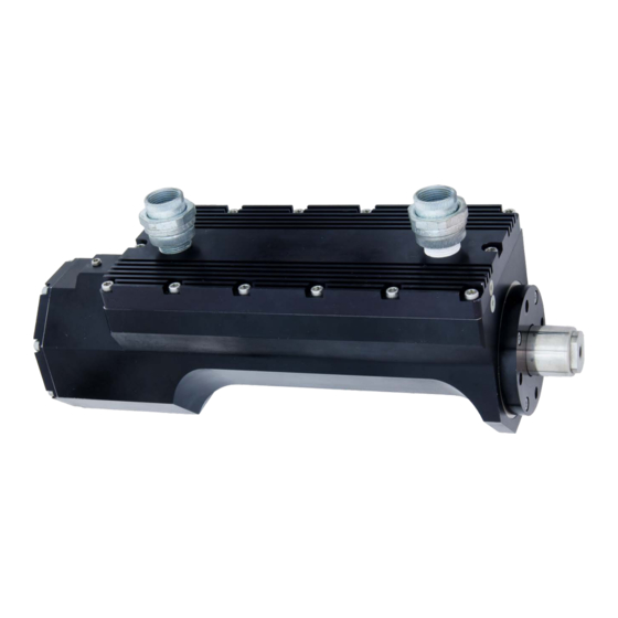
ACT1000/ACT1000HF Electric linear actuator
SD-6029 Rev 2
April 2018
WARNING – This information is subject to the export of which is restricted by the Export
Administration Act and the Export Administration Regulations (EAR), 15 C.F.R. parts 730-774,
diversion contrary to U.S. law is prohibited. The export, re-export, transfer or re-transfer of this
technical data to any other company, entity, person, or destination, or for any use or purpose other
than that for which the technical data was originally provided is prohibited without prior written
approval and authorization under applicable export control laws.
EAR Export Classification: ECCN: EAR99
Meggitt Control Systems
11661 Sorrento Valley Road, San Diego CA 92121, USA
Precision Engine Controls Corporation d/b/a Meggitt Control Systems
Tel: +1 (858) 792 3217
Fax: +1 (858) 792 3200
www.meggitt.com
Advertisement
Table of Contents

Subscribe to Our Youtube Channel
Related Manuals for Meggitt ACT1000

Summary of Contents for Meggitt ACT1000
- Page 1 EAR Export Classification: ECCN: EAR99 Meggitt Control Systems Tel: +1 (858) 792 3217 11661 Sorrento Valley Road, San Diego CA 92121, USA Fax: +1 (858) 792 3200 www.meggitt.com Precision Engine Controls Corporation d/b/a Meggitt Control Systems...
- Page 2 SD-6029, Rev 2 This manual provides installation and operating instructions for the ACT1000/ACT1000HF electric linear actuator. Every attempt has been made to provide sufficient information in this manual for the proper operation and preventive maintenance of the actuator. Read this manual in its entirety to fully understand the software.
-
Page 3: Table Of Contents
SD-6029, Rev 2 TABLE OF CONTENTS Purpose of this guide What the user should know Related publications Installing the ACT1000/ACT1000HF Before beginning General specification summary Mechanical installation Electrical connections Understanding the ACT1000/ACT1000HF System description Electrical description Mechanical description Operating the ACT1000/ACT1000HF... -
Page 4: Purpose Of This Guide
This publication is designed to help the user install, operate, maintain, and troubleshoot the ACT1000/ACT1000HF electric linear actuator. What the user should know To install, operate, and troubleshoot the ACT1000/ACT1000HF, it is necessary for the user to have a fundamental understanding of: • Electronics concepts such as voltage, current, and switches •... -
Page 5: Installing The Act1000/Act1000Hf
Before beginning Inspection The ACT1000/ACT1000HF should be inspected immediately after unpacking. Check for dings or dents or any other obvious signs of damage. Check for any damage to the threads of the conduit unions and that the power and signal wires are in good condition. - Page 6 SD-6029, Rev 2 Figure 1-2 ACT1000HF identification nameplate Figure 1-1 ACT1000 identification nameplate WARNING – This information contains technical data subject to the EAR: ECCN: EAR99 Page 6 of 50...
- Page 7 SD-6029, Rev 2 Recommended installation process Users must determine if it is best to couple the ACT1000/ACT1000HF to the load before or after the installation has been tested. • Review general specifications such as load and stroke length • Mechanically connect the clevis or flange of the ACT1000/ACT1000HF •...
-
Page 8: General Specification Summary
Baud rate (bps): 9600, 19200, 38400, 57600 (default), 115200 HART Performance All performance values are based on use with the ACT1000/ACT1000HF in default configuration. Any changes to the ACT1000/ACT1000HF internal settings to change stroke profile will alter performance values. 4.5 in/sec (ACT1000) -
Page 9: Mechanical Installation
5.4 in x 6.1 in x 16.7 in (not including wiring conduits) Weight 40 lbs Mechanical installation This section describes proper ACT1000/ACT1000HF installation. It is advised to confirm compliance with factory recommendations. Mounting orientation and product dimensions The ACT1000/ACT1000HF can be mounted in any directional orientation, whether horizontal, vertical, or at an angle. - Page 10 SD-6029, Rev 2 Figure 1-3 ACT1000/ACT1000HF envelope dimensions. Pin-mount provisions also shown. WARNING – This information contains technical data subject to the EAR: ECCN: EAR99 Page 10 of 50...
- Page 11 SD-6029, Rev 2 Figure 1-4 Additional overall dimensions and earth bonding connection dimensions. WARNING – This information contains technical data subject to the EAR: ECCN: EAR99 Page 11 of 50...
- Page 12 SD-6029, Rev 2 Figure 1-5 Mounting provisions for flange-mount. WARNING – This information contains technical data subject to the EAR: ECCN: EAR99 Page 12 of 50...
- Page 13 Lifting hazard – Do not attempt to hand-lift the actuator. Use appropriate lifting equipment. Mounting using the clevis The ACT1000/ACT1000HF features a clevis for securing the motor end of the actuator. A high-strength shoulder bolt (0.375” diameter) is recommended to fasten the actuator to a user-provided mounting bracket.
-
Page 14: Electrical Connections
Appropriate wire connection hardware and a 0.250-20 UNC - 2A screw should be used to connect the case of the ACT1000/ACT1000HF to the same ground plane as the user’s WARNING – This information contains technical data... - Page 15 The ACT1000/ACT1000HF operates on a nominal 120VDC, user-provided input voltage, which is supplied to the unit through the integral two-wire power harness. The length of the power harness is 90 inches. See Table 1-1 for the wire list for the ACT1000/ACT1000HF power harness.
- Page 16 This test should be performed at both the minimum and maximum expected operating voltages Also, the output capacitance should be carefully positioned so that it is never disconnected from the ACT1000/ACT1000HF power input during any contact or switching operations.
- Page 17 Table 1-3 Wire size for power harness Signal connections Signals are sent between the ACT1000/ACT1000HF and the user’s controller through the integral 25-wire signal harness. The length of the signal harness is 90 inches. See Table 1-4 for the wire list for this harness.
- Page 18 US Group B hazardous locations, an explosion proof seal must be placed within 18 inches. CAUTION Disconnect all ACT1000/ACT1000HF connections prior to welding. Note: For proper operation of the controller, the voltage between the control inputs and the negative terminal of the power supply should be below 200 VDC.
- Page 19 SD-6029, Rev 2 ACT1000/ACT1000HF 4-20mA CONTROLLER 4-20mA INPUT OUTPUT POSITION MTR CURRENT Ω <500 POSITION RTN MTR CURRENT RTN Figure 1-7 Typical analog output connection Discrete inputs The discrete inputs are 24 VDC ON (High) and 0 VDC OFF (Low). They are electrically isolated up to 500 VAC.
- Page 20 SD-6029, Rev 2 RS485 port ACT1000/ACT1000HF SERIAL A(-) INTERFACE TRANSCEIVER B(+) Figure 1-10 Typical RS485 serial interface connection Note: An isolated USB-RS485 adapter is recommended, such as B&B Electronics USOPTL4. Note: The maximum typical distance for RS485 serial connection is 2300 ft at 57.6 kbps.
- Page 21 SD-6029, Rev 2 Distance to user’s Recommended controller wire size (Minimum) ≤ 1000 ft. AWG 18, stranded > 1000 ft. Consult factory Table 1-5 Wire size for signal harness Note: Use a separate conduit for the signal wiring. This prevents noise pickup and transmission from ancillary equipment, which could cause instability in the actuator.
- Page 22 SD-6029, Rev 2 Intentionally blank WARNING – This information contains technical data subject to the EAR: ECCN: EAR99 Page 22 of 50...
-
Page 23: Understanding The Act1000/Act1000Hf
Power The ACT1000/ACT1000HF operates on a nominal input voltage of 120 VDC that is provided by the user via an integral power harness. Refer to the general specification summary table in Section 1.2 for load specification values. - Page 24 The RESET command is a user-provided discrete input to the ACT1000/ACT1000HF. This command causes the ACT1000/ACT1000HF to clear any faults with conditions that are within limits, shut off the motor drive, and reset the unit to its initialization state with the home position cleared.
- Page 25 Figure 2-1 ACT1000/ACT1000HF Electronics system block diagram Alarms The ACT1000/ACT1000HF provides two two-wire alarm signals via the signal harness. The discrete alarm outputs are solid-state switches that are normally closed (open for fault or powered down condition). The user’s controller provides +24 VDC to complete the circuit.
-
Page 26: Mechanical Description
The main housing also contains rigid mechanical stops to prevent travel of the extension rod beyond designed limits. Brushless DC motor assembly A brushless DC motor powers the ACT1000/ACT1000HF linear drive mechanism. The DC motor consists of a stator and rotor. Motor stator The motor stator is attached to the main housing by a pre-loaded wave spring and radially-acting set screws. - Page 27 Resolver assembly A brushless resolver is the primary ACT1000/ACT1000HF position feedback sensor. Resolver excitation is achieved via a sinusoidal signal from the MCE. Also, the resolver provides two sinusoidal feedback signals to the MCE that are used to calculate shaft angular position.
- Page 28 SD-6029, Rev 2 Intentionally blank WARNING – This information contains technical data subject to the EAR: ECCN: EAR99 Page 28 of 50...
-
Page 29: Operating The Act1000/Act1000Hf
Finding home position When the status check and other steps in the Power-up/Reset process are complete, the ACT1000/ACT1000HF will wait until it receives the RUN command. At this point, the ACT1000/ACT1000HF has no information about the position of the extension rod. -
Page 30: Holding Motor Current State
SD-6029, Rev 2 Once the home position has been established, the DEMAND current determines subsequent positioning of the actuator within its programmed span. See Section 3.8 for additional information about Set-Up parameters. Holding Motor Current state In the Holding Motor Current state, the actuator holds the home position with a configurable maximum holding force. - Page 31 RUN = ON > 4.1 mA Move to DEMAND position Move to RUN = ON Stop position Figure 3-1 ACT1000/ACT1000HF basic operation flow chart WARNING – This information contains technical data subject to the EAR: ECCN: EAR99 Page 31 of 50...
-
Page 32: Moving To Stop Position
Home position The home position correlates to a DEMAND signal of 4 mA. The home position is determined after power up or after the ACT1000/ACT1000HF has been reset. Deadband While the home position correlates to a DEMAND signal of 4 mA, the actuator will only move for DEMAND signals ≥... - Page 33 SD-6029, Rev 2 Full span position The full span position correlates to a DEMAND signal of 20 mA. The span is specified in the Set-Up parameters and has a default value of 5.9 inches of extension (the default definition of home is retract, so default span is an extension).
- Page 34 SD-6029, Rev 2 Figure 3-2 Actuator position vs. DEMAND; Home as mechanical stop in actuator Figure 3-3 Actuator position vs. DEMAND curve; Dead band description WARNING – This information contains technical data subject to the EAR: ECCN: EAR99 Page 34 of 50...
-
Page 35: Resetting The Actuator
Figure 3-4 Actuator position vs. DEMAND curve; mechanical stop in user’s system Resetting the actuator To reset the ACT1000/ACT1000HF, +24 VDC must be applied across the RESET (aka fault clear) wires for at least 22 milliseconds. The leading edge of the RESET command triggers a reset of the faults, clears the home position, and resets the device to the initial idle state (similar to power up state). -
Page 36: Monitoring System Health
When the ACT1000/ACT1000HF detects a system fault, it opens the fault circuit designated for that particular fault. If a fault alarm is detected, the user should shut down the ACT1000/ACT1000HF to investigate the failure cause. Removing 120 VDC power shuts down the ACT1000/ACT1000HF. - Page 37 SD-6029, Rev 2 Fault category Fault Fault name Low limit High limit Persist time, Auto Warning name number sec (cfg) reset of /Shutdn fault flags (cfg) 3.3V (pos and neg) POS3V3_LO 2.97 POS3V3_HI 3.63 Warning NEG3V3_LO -3.63 NEG3V3_HI -2.80 Tracking TRACKING 3.3% 10.0...
-
Page 38: Changing Setup Parameters
ACT1000/ACT1000HF via the RS485 interface using PECC’s ActWiz software. The Set-Up parameters can only be accessed when the ACT1000/ACT1000HF is in the Set-Up state. See the basic operation flow chart in Figure 3-1 and the Set-Up State section below for details. - Page 39 SD-6029, Rev 2 Power up/standby and set up states The ACT1000/ACT1000HF is in power up/standby state immediately after it has been powered up or reset. The Set-Up state is entered by sending the setup command, which is done automatically by ActWiz when parameters are downloaded by the software. The Set-Up state is accessible only from the power up/standby state or from the shutdown state.
- Page 40 SD-6029, Rev 2 Intentionally blank WARNING – This information contains technical data subject to the EAR: ECCN: EAR99 Page 40 of 50...
-
Page 41: Maintaining The Act1000/Act1000Hf
Refurbishment PECC recommends that the ACT1000/ACT1000HF be shipped back to the factory for refurbishment when the user’s system is shut down for overhaul (typically after approximately 40,000 hours of operation.) Contact PECC for details about refurbishment. - Page 42 SD-6029, Rev 2 Intentionally blank WARNING – This information contains technical data subject to the EAR: ECCN: EAR99 Page 42 of 50...
-
Page 43: Troubleshooting
(DVM), and computer with diagnostic software. The ACT1000/ACT1000HF is comprised of highly reliable components and should not develop service problems under normal operating conditions. However, over a period of time and service, failures may develop. - Page 44 SD-6029, Rev 2 Symptom Probable causes Corrective action Actuator inoperative - Power wires not connected FAULT alarm Ensure 120 VDC primary system power at actuator No or low 120 VDC power Actuator inoperative - No RUN or position command Ensure 24 VDC RUN and position command at NO FAULT alarm actuator Actuator moves toward...
- Page 45 For troubleshooting purposes, use Table 5-3 to verify the actuator electrical continuity integrity. Disconnect the ACT1000/ACT1000HF power and digital harnesses and use a digital multi-meter (DMM) to check the resistance values between the wires indicated on the table. If an open circuit is detected, send the ACT1000/ACT1000HF to PECC for test and repair.
- Page 46 MOTOR CURRENT High impedance POSITION High impedance Warning FAULT Alarm High impedance Shutdown FAULT Alarm High impedance Table 5-3 ACT1000/ACT1000HF Electrical continuity troubleshooting chart WARNING – This information contains technical data subject to the EAR: ECCN: EAR99 Page 46 of 50...
-
Page 47: Appendix A: Decomissioning And Disposal
SD-6029, Rev 2 Appendix A: Decommissioning and disposal This section contains recommended ACT1000/ACT1000HF decommissioning and disposal practices. It is for permanent removal or replacement of the installed product, with no intention of rework, overhaul, or use as a spare. For removal, follow proper lockout /tagout procedures and verify no live electrical circuits: •... - Page 48 SD-6029, Rev 2 Intentionally blank WARNING – This information contains technical data subject to the EAR: ECCN: EAR99 Page 48 of 50...
-
Page 49: Appendix B: Glossary
A 4 mA to 20 mA signal that communicates the actual actuator position to the controller. Motor current feedback A 4 mA to 20 mA signal that is proportional to ACT1000/ACT1000HF motor current. The signal is scaled with Max. Force. FAULT (WARNING) alarm A discrete signal from the ACT1000/ACT1000HF that communicates an internal failure. - Page 50 SD-6029, Rev 2 Intentionally blank WARNING – This information contains technical data subject to the EAR: ECCN: EAR99 Page 50 of 50...
Need help?
Do you have a question about the ACT1000 and is the answer not in the manual?
Questions and answers